MACHINE VISION - High-speed 3-D machine vision: getting the details right
When moving from low- to high-speed 3-D machine vision, many new challenges come into play. Hardware decisions involve not just the camera, but the data connection, the analysis and control algorithms, and the data storage.
JOHN NAGLE
With any machine-vision system, a collection of disparate components-cameras, lighting, computers, and software-must work together to acquire an image, analyze the image, and usually take some action as a result of that analysis. With high-speed systems, each of these components becomes more critically significant to the system as a whole because each part is being asked to perform at a much more intense level. An imbalance will result in poor-quality images that confuse the analysis software. Worse, any anomaly that interrupts or impedes the flow of data can bring it all crashing to a halt. Many factors must be considered when implementing a high-speed 3-D machine-vision system.
Camera systems
The first and most important decision to make when choosing a machine-vision system is what acquisition hardware should be used. Aside from being able to sustain the data rate required, considerations include environmental factors (such as temperature and moisture), sensor size, resolution, and more. Also important is how much of the computational workload is handled by the camera; the more the camera does, the less the vision software will have to do.
In one scenario, a conventional machine-vision camera for 3-D line scanning is used. In this case, the software receives a full-frame buffer of information and the software analyzes and locates the laser line. It is certainly the slowest approach, but it can minimize the hardware costs, and users will have the greatest amount of flexibility as to how the image gets converted into a profile. An unavoidable result is that the software now has a lot of work to do before it can even begin to analyze the geometry of the image. While most applications that use this approach measure performance in single- or double-digit frames per second, our projects at Nagle Research usually involve many thousands of frames per second.
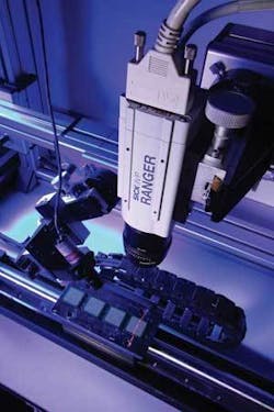
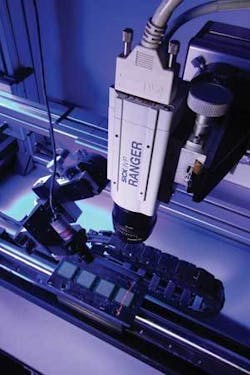
When is this kind of speed necessary? It depends. When intermittently sampling a uniform shape with relatively large problem areas, slower speeds might be acceptable. When moving a complex part at more than a few inches per second, something faster would be necessary. For example, a camera made by SICK (Minneapolis, MN) operates at up to 30,000 profiles per second at a resolution of 1536 × 512 pixels and includes onboard algorithms for measurement (see Fig. 1).
These algorithms reside in the camera firmware, with direct access to the sensor, and therefore are very efficient at converting raw data from the sensor into a usable profile. Some algorithms are more robust (and slower) than others, analyzing the Gaussian distribution of a scanning-laser line in different ways. Whatever sort of camera system is ultimately used, having onboard algorithms to generate profile data from a raw sensor image should be an important factor in deciding on the system.
Acquiring the image
The three most common connections between a computer and camera are Firewire (IEEE-1394), Camera Link, and Gigabit Ethernet (GigE). Firewire is the overall cheapest route; the cameras are usually the least expensive and acquisition hardware exists on most every computer made in the last three years. It is also the slowest of the three; most cameras in this category cap at 60 frames per second. Camera Link is extremely fast, but has drawbacks that include expensive frame-grabber boards, the requirement of shorter cabling, and high complexity in software development. GigE is relatively new, but has shown great promise. The data rates are high, cables can be very long, and the hardware is very inexpensive. The only real downside is that the computer “wastes” some CPU cycles to receive the image, whereas Camera Link offloads that task into separate hardware.
Illumination
At high speeds, the imaging sensor will have far less time for exposure than in a conventional system. There are two ways to get the intensity up to a usable level: increase the amount of time the sensor is exposed to light, or increase the amount of light entering the lens. With high-speed 3-D, the illumination source must often be made more intense.
The color and type of material being profiled can play a significant role in deciding laser requirements, as well as ambient lighting conditions. Darker material (rubber, for example) soaks up light like a sponge. Conversely, light-colored objects reflect light very well, and therefore can reduce or eliminate the need for higher-power lasers. Scanning items that contain multiple materials, such as metal parts with rubber linings, is particularly challenging, and can require filters to reduce hot spots on the sensor. With particularly shiny or translucent objects, light either reflects perfectly in one direction or passes through the object without reflecting at all, and in such cases it can be very difficult (but not impossible) to get a usable profile.
Software considerations
Machine-vision software can be broadly divided into three specific tasks: acquisition, analysis, and control. In the acquisition phase, data is received from the camera through whatever conduit is used (Camera Link, Firewire, or GigE). The data is then analyzed using whatever algorithms are required. Finally, an action is taken as a result of the analysis: communicating with a programmable-logic controller, writing data to a local hard drive, interaction with a server, and so on.
Acquisition is rarely a problem; generally speaking, most modern computer hardware can readily absorb the data being fed to it by the camera. The challenge is in the development of the analysis and control algorithms, which have to process the data stream fast enough to ensure that the data does not begin to queue up. At the frame rates normally used in high-speed applications, even a generous onboard data buffer can fill very quickly. For truly high performance, the imaging application needs to be written in C or C++. So-called “Dot Net” (.NET) development-platform languages such as VB and even C# incur a significant performance penalty, resulting in less processing time. If a .NET language must be used due to company policies, performance-critical code can still be written in C/C++ and incorporated as a DLL (a Microsoft Windows dynamic-link library).
Everything the software does with the data it collects has a direct impact on the maximum sustainable data rate. The software engineer needs to be extremely careful to make sure that the logic flow results in timings that are deterministic; that is, given any acceptable input condition the resulting logic timing will never exceed ∆t, with ∆t being defined as the shortest time between consecutive inputs.
As an example, consider an application in which batches of parts must be processed, each batch is in a container exactly four feet in length. For each discrete batch, the software must find all the edges and store the resulting bitmap on the hard drive. Assuming the edge-detection technique used is a convolution filter, there will be a fixed number of “multiply” operations (a series of matrix multiplies) to generate the resulting image. The detail and complexity of the 3-D image in this case is entirely irrelevant; one part or 1000 parts will take the same amount of time to process.
Situations that can be tricky involve operations that first enumerate discrete parts, and then perform operations on each located part individually. Let’s say the application required looking at batches of randomly scattered pencils to make sure the wood is cut to the proper length and the surface has no obvious blemishes. The software must first locate each pencil and then de-skew, measure, and analyze them. The processing time for each batch is entirely dependent on how many pencils are present. In such cases, profiling tools such as the Vtune performance analyzers (Intel, Santa Clara, CA) or other microsecond-resolution timing routines should be used to determine how long it takes to process a single pencil, and design the software to accommodate the worst-case pencil count.
For local hard-drive storage, keep in mind that hard drives do not write at the same continuous speed over the entirety of the drive, so check the manufacturer’s specs and plan for the worst case (with whatever margin of safety is comfortable). Ideally, there should be no other file operations occurring on the data drive, as moving the read/write head around drastically slows the maximum data rates. Even something as innocuous as writing data to a debug or log file can cause big problems when the data file gets too large. With network storage, there can be some of the same problems as local storage, along with the additional network traffic that exists that might impede the transmission of the data. Whatever storage is used, run performance tests over the entire drive and monitor the size of the frame-buffer backlog to make sure it can keep up.
Scanning railroad tracks
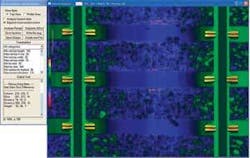
One interesting application we developed is for a client who needs a high-speed railroad-analysis system. Two 3‑D cameras running at more than 5000 frames per second are used to acquire a 3-D image of the entire width of the track (9 ft) at a resolution of 0.04 in. or better in all axes (see Fig. 2). The scanning vehicle travels at 30 mph. In this case, the number of different defects to detect and the algorithm complexity mean that it is not possible to do the analysis in real time; therefore, the only critical factor is that the hard drives must be capable of writing the data. Additional electronics were developed to quickly burst the GPS (global-positioning-system) and rail-temperature data across the USB port. The GPS units output NMEA (National Marine Electronics Association, a GPS protocol) data very slowly via serial interface and rail-temperature data exist only as raw analog signals. Offloading the transfer of this nonvision data to separate hardware allows the computer to devote all system resources to receiving the data, building the profile records, and writing the data unimpeded.
JOHN NAGLE is the president and founder of Nagle Research, 13809 Research Blvd., Austin, TX 78750; e-mail: [email protected]; www.nagleresearch.com.


