Researchers at the University of Neuchâtel (Neuchâtel, Switzerland) have demonstrated a micro-optical switch that has better performance for applications where a signal from a single input fiber must be switched into one of many receivers. The switch uses a micromachined deformable mirror to correct aberrations introduced when a refractive lens is displaced off-axis to achieve switching. The mirror allows the coupling efficiency to be maintained despite increasing fiber number and thus lens displacement—a situation that is not true with a conventional flat-mirror refractive-lens switch. Though the adaptive mirror is as yet difficult to fabricate, the system has been shown to work well, with high coupling efficiency and low crosstalk maintained despite increasing numbers of output fibers.
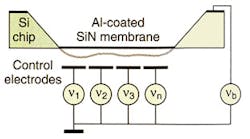
The switch uses a four-focal-length system (see Fig. 1). Moving the lens laterally shifts the point to which the input is imaged, and so changes the switch position. Ordinarily, this kind of system relies on the receiving fibers being close to the optical axis, because the further away they are, the more aberrated the image. As a result, coupling efficiency drops when switching to fibers further from the bundle center, so the bundle has to either be kept small or the efficiency accepted as low. Replacing the passive, flat mirror with an active, deformable one allows compensation for these aberrations and so removes the size restriction. To this end, the researchers designed a chip with an aluminum-covered silicon nitride membrane that could be pulled toward an array of electrodes beneath when a voltage was applied (see Fig. 2). By varying the voltages across each electrode, the pull, and therefore the shape, could be varied.
An important part of the project's success was the algorithm that allowed the team to determine the best mirror shape for a given system configuration, with the mirror correcting for the first 15 Zernike polynomials. This problem is not easily solved analytically, so the Swiss team chose to solve it using a so-called genetic algorithm, using the Zernike coefficients as the genetic code and the breeding process based on performance in the real system.
Once optimized, the system worked well: coupling efficiency remained more-or-less steady as the image was switched to further-out receiver fibers (there were 30), with a maximum 51% and minimum 25% coupling efficiency. Though there was significant variation across the array, the curve itself was relatively flat. With the flat mirror, a coupling efficiency started out higher, at 60%, but rapidly dropped to below 20% at 10 fibers from the center and less than 10% at 16. The deformable-mirror system also showed undetectable crosstalk (less than -30 dB).
The researchers would like to enhance performance even further, however, pushing closer to the theoretical maximum coupling efficiency of 78%. They have already identified two areas of improvement: voltage supply (fluctuations mean the shape of the mirror is not maintained properly), and difficult-to-correct astigmatism caused by residual stress in the mirror. Mirrors that are almost stress-free, they say, have been reported by others: applied to their device, this improvement could boost coupling efficiency by 10%. Other areas of future research will involve experimenting with different electrode-array structures that could help reproduce the required mirror structure more faithfully.
REFERENCE
1.Yves-Alain Peter et al., IEEE Phot. Tech. Lett. 14 (3), 301 (March 2002).
About the Author
Sunny Bains
Contributing Editor
Sunny Bains is a contributing editor for Laser Focus World and a technical journalist based in London, England.


