Smart amplifiers adapt to changing loads in WDM systems

One early allure of erbium-doped fiber amplifiers was the possibility that they would make it easy to upgrade fiberoptic systems. The hope was that transmission capacity could be upgraded merely by adding new terminal equipment for extra channels or higher speeds without having to adjust optical amplifiers or the transmission network. Unfortunately, that goal proved elusive as system speeds and channel counts increased. Move to higher data rates, and dispersion can impair system operation. Add new optical channels, and the balance of gain between wavelengths shifts, causing troublesome differences in power across the amplifier's gain spectrum.
Today, standard optical amplifiers may require adjustment every time an optical channel is added to or subtracted from the signal they carry. Sending technicians to do the job adds to the costs and delays of network provisioning, but this approach works as long as the network is relatively static. It won't work for future dynamic networks, in which channel loads change continually and transmission paths must be repeatedly reconfigured. Dynamic networks will require "smart amplifiers," which can adapt automatically to changing loads or can be adjusted remotely to handle changing requirements. Developing those smart amplifiers poses serious challenges, but progress has been encouraging.
Physical considerations
Erbium-doped fiber amplifiers are far from theoretically "ideal" amplifiers that would treat all input signals equally. One reason is that erbium gain varies with wavelength, with a peak near 1535 nm. The exact shape of the gain profile depends on the length and doping of the fiber amplifier, the pump power, and the input power. As input powers increase, the variation of gain with wavelength declines, giving a more uniform gain spectrum.
Gain curves flatten at higher powers because of a second important effect: gain saturation with increasing input power. This is evident even in a single-channel system, in which an amplifier with small signal gain of 30 dB can boost a weak 1-μW input to a 1-mW output. However, if the amplifier's maximum output is 10 mW, the gain is limited to 20 dB when the input signal is 100 μW.
Gain saturation occurs when the input signals across the entire gain spectrum are strong enough to produce stimulated emission from all the excited erbium atoms in the fiber. The process is not particular about the wavelengths being amplified, as long as they fall within the erbium gain band so they can stimulate emission. From a simplified viewpoint, if an amplifier has maximum output of 10 mW, it can emit all that power at one wavelength, amplify four channels to 2.5 mW each, amplify ten channels to 1 mW each, or amplify each of 40 channels to 0.25 W. Thus, going from four to five channels would drop the power per channel from 2.5 to 2 mW, and doubling the number of channels from four to eight would drop the power from 2.5 to 1.25 mW, a 3-dB drop. (In practice, the power would not be distributed evenly among all channels.)
Changing channel count and distribution also can affect nonlinear effects in amplifiers, such as the transfer of optical power between channels via stimulated Raman scattering.
Static gain equalization
Small differences in gain are inevitable across the operating range of fiber amplifiers. These can be tolerated in systems containing only a few amplifiers, but become a serious problem after a long chain of amplifiers. If gain is consistently just 1 dB higher on one channel than on a second, the differential grows to 10 dB after 10 amplifiers, and the weaker channel risks getting lost in the noise.
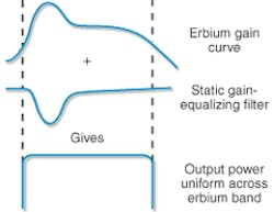
The simplest form of static gain equalization is to add filters that offset the extra gain (see Fig. 1). This technique is widely used in present long-haul systems. A more complex alternative is to add a Raman amplifier stage, which has peak gain at longer wavelengths that can balance the peak gain at shorter wavelengths in erbium-fiber amplifiers. Raman amplification also has other attractions, such as low noise and reducing nonlinear effects, which have earned it a place in high-performance fiber systems.
However, static gain equalization can't compensate for dynamic changes arising from adding or dropping optical channels, nor can static techniques cope with temperature changes or other effects that can subtly alter amplifier characteristics.
The smart amplifier
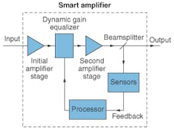
Coping with dynamic networks requires smart amplifiers that sense changes in the transmitted signal and automatically adjust their optical properties in response. This requires adding two key elements to an ordinary amplifier: a sensor array and adjustable optical elements. Like an optical performance monitor, the sensor array measures power at each wavelength. An electronic system then analyzes those power measurements and calculates what needs to be done to equalize gain across the amplifier's operating range. Then this feedback is applied to a device placed before the sensor, such as to a dynamic gain-equalizing filter between a pair of amplification stages (see Fig. 2).The "smart" part of the amplifier is the feedback loop that senses change in the output signal and uses that information to control the gain. It works automatically, so it can adapt to system fluctuations or component failures as well as to intentional changes in the number of channels transmitted. This makes the technique more powerful than mere remote control of amplifier adjustments in response to changes in system provisioning.
Gain can be equalized by adjusting either the loss or the gain of optical elements. Static gain equalization uses both attenuators and Raman amplifiers to ensure uniform response. Conceptually, gain could be equalized dynamically by continually adjusting the gain of an amplifier stage, but so far most work has been done with dynamic gain-equalizing filters.
Dynamic gain-equalizing filters
Dynamic gain equalization requires a filter that varies its transmission as a function of wavelength. One approach is to equalize gain channel by channel, but the drawback is that most types require complete demultiplexing of the optical signal and a feedback loop and filtering element for each optical channel. An alternative is a single dynamic gain-equalizing filter, typically containing multiple elements, that adjusts transmission over the amplifier's entire range. Several types have been developed based on different technologies, and a few have begun trickling onto the market.
One concept is an all-fiber, tunable acousto-optic filter developed by Novera Optics (San Jose, CA). An acoustic transducer induces a low-amplitude acoustic wave in a short stretch of fiber. Interactions of the acoustic wave with the fiber affect transmission properties in a narrow band of wavelengths, so the fiber serves as a notch filter. A single transducer produces one narrow notch, with the modulation strength and frequency determining the wavelength. To cover a wider range, the transducers can be stacked in series along a fiber, with each one attenuating a different band. Digital processors can combine the notch response of several filters to produce the desired attenuation spectrum. Novera says it can closely model the ideal equalization spectrum using eight transducers to cover the C-band of erbium-fiber amplifiers with response time rated at 50 μs (see Fig. 3).Chorum Technologies (Richardson, TX) also synthesizes a complex equalization filter profile by assembling a series of variable-attenuation modules. However, each stage of its module is a liquid-crystal filter with transmission that varies cyclically with wavelength—for example, with a peak every 10 nm. Each stage has a different wavelength variation at a harmonic of the basic frequency, plus a liquid-crystal attenuator that varies the amplitude of this cyclic variation. The sum of the harmonic responses of several stages gives the required equalization curve.1
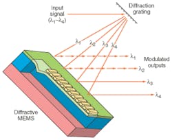
Diffractive MEMS technology is another alternative used by LightConnect (Newark, CA). The device consists of an array of reflecting ribbons suspended above a reflective surface, with space between the ribbons to allow some light to reach the surface. When the ribbons are exactly one wavelength above the surface, the light reflected from them is in phase with light reflected from the surface, so the structure is reflective. When the ribbons are moved one-quarter wavelength closer to the reflective surface, light reflected from them is out of phase with that reflected from the surface, causing destructive interference that diffracts the light at other angles. To make a dynamic wavelength-selective filter, a grating spreads a spectrum across several stripes, which are modulated so the reflectivity varies with wavelength (see Fig. 4). Because the movement is very small, the material should not experience significant fatigue, and the technique has the potential to modulate individual channels.Planar waveguide technology also can be used to make integrated dynamic equalizing filters. In versions offered by Agere Systems (Breinigsville, PA), an initial stage breaks the signal into several bands and directs them through an array of interferometric thermo-optic modulators. Control of the temperature of each waveguide stripe determines the attenuation of that band. Then the bands are recombined to produce the output signal. The Agere device is an outgrowth of earlier work at Bell Labs, which produced dynamic channel-equalizing filters.2 Those devices separated all channels in a system so they can compensate each one precisely, making them attractive for high-performance long-haul systems with high channel counts.
For less demanding applications, CoAdna Photonics (San Jose, CA) has combined a static gain-equalization filter with a system that dynamically controls the "tilt" of attenuation with wavelength. The idea is based on the observation that much of the dynamic variation in erbium-amplifier gain is across a wide range of wavelengths. For example, as channel loading changes, the gain may increase at shorter wavelengths but decrease at longer wavelengths. This tilt can be compensated with a single element that changes its attenuation profile over a range of wavelengths—from high attenuation at short wavelengths to low attenuation, and vice versa. Although the gain equalization is not ideal, it may be adequate for many applications.
Other approaches
So far, adding dynamic gain-equalizing filters to erbium-fiber amplifiers is the leading approach to building smart amplifiers. However, the technology remains in its infancy, and other concepts are possible. Dynamically modulating amplifier gain as a function of wavelength seems easier for Raman amplification than for erbium-fiber amplifiers, because Raman gain profiles depend directly on the pump wavelength. At least in theory, modulating the powers of several pump lasers at different wavelengths offers a way to modulate the Raman gain spectrum dynamically. Semiconductor optical amplifiers offer another possibility.
In the long term, the key to success will be helping telecommunications carriers to reduce their equipment and operating costs. The challenge will be bringing the cost and performance of smart amplifiers to the levels the carriers want.
ACKNOWLEDGMENT
Thanks to Eric Gustafson of LightConnect.
REFERENCES
1. J-C Chiao, "Liquid crystal optical harmonic equalizers," paper presented at IEEE LEOS 2001 Summer Topical Meetings (July 30-Aug. 1, 2001).
2. C. R. Doerr et al., IEEE Photon. Tech. Lett. 12, 1195 (September 2000).
About the Author
Jeff Hecht
Contributing Editor
Jeff Hecht is a regular contributing editor to Laser Focus World and has been covering the laser industry for 35 years. A prolific book author, Jeff's published works include “Understanding Fiber Optics,” “Understanding Lasers,” “The Laser Guidebook,” and “Beam Weapons: The Next Arms Race.” He also has written books on the histories of lasers and fiber optics, including “City of Light: The Story of Fiber Optics,” and “Beam: The Race to Make the Laser.” Find out more at jeffhecht.com.


