Photonic Frontiers: LEDs - UVC LEDs reduce marine biofouling
Although biofouling costs marine, shipping, and other global industries billions of dollars every year, it rarely generates the media attention reserved for other environment-related issues. But rest assured, biofouling is garnering plenty of attention from the sensor industry, which is developing a range of UVC (250–280 nm) LED-based instruments that help measure and minimize biofouling's impact, or prevent it from happening altogether.
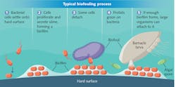
Biofouling occurs when microorganisms in water attach to wet surfaces. These "pioneer bacteria" then begin to multiply, gradually covering the surface with biofilm. Eventually, other organisms attach to the biofilm, making it difficult (and expensive) to remove (see Fig. 1).
Biofouling costs the shipping industry an estimated $7.5 billion every year. Most of that cost is reflected by ships having to burn 40% more fuel to overcome the drag that results from biofouling build-up on a vessel's hull. In addition, burning more fuel increases the ship's carbon dioxide and sulfur dioxide emissions.
Biofouling also impacts coastal and marine research organizations, which rely on a range of sensors to monitor the environmental condition of oceans and coastal waters. Left unchecked, the biofilms have been known to render some sensors inoperable within a week or two of deployment.
As a solution, UVC (ultraviolet C) LED-based devices are being developed to detect biofilm growth on a vessel's hull early on, thereby making biofilm removal easier. And LEDs are now being placed within marine sensors to deactivate the microorganism's DNA and prevent the biofilm from developing in the first place.
Shipping industry
If it is caught early enough, biofilm on a ship's hull can be removed and will stay away for a relatively long period of time. Removal is far more difficult in the later stages, and can be too little, too late because of corrosion-related damage.
So, shipping companies have long sought a way to monitor and predict biofouling progress so they can optimize their vessel maintenance/cleaning schedules. The current cost of poorly timed hull cleaning is roughly $1 billion per year. With monitoring and better prediction capabilities, it is believed that the cost can be reduced substantially.
Scientists at the Helmholtz Centre for Ocean Research and the Institute of Physical Chemistry, Christian-Albrechts-University (both in Kiel, Germany) have developed a robust and reliable marine-environment sensor that can help the shipping industry detect and monitor biofilm formation in situ and nondestructively.1 To date, their experiments have provided, for the first time, a way to continuously monitor biofilm formation in its natural habitat. Their prototype UVC LED-based spectroscopy instrument, which has been field-tested to monitor early biofilm growth on large areas (like a ship's hull), is designed to operate autonomously over several months, with the ability to distinguish between organic and inorganic materials.
Here's how it works: Analytical labs have long employed optical detection analyses, via absorption or fluorescence methods, to detect and analyze various compounds. However, the complexity, size, and cost of traditional instrumentation restricted the development of in situ applications. LEDs—with their smaller footprint, lower cost, and stable light output—were thought to be the answer, but early sapphire-substrate-based LEDs in the 250–280 nm range had life expectancy, performance, and reliability issues.
Those issues were resolved, however, with the introduction of new lattice-matched LEDs fabricated on single-crystal aluminum nitride (AlN) substrates. With approximately 10,000 fewer defects per square centimeter, these LEDs deliver more light and have a substantially longer service life. As a result, UVC LEDs are now the primary driver behind a new and expanding generation of in situ or portable diagnostic instruments.
All microorganisms contain natural intracellular fluorophores that are ideal for fluorescence-based detection. Fluorescence provides high sensitivity and selectivity, fast response time, and can be monitored in situ, in large areas, without actual sample contact. At UV-range wavelengths, intrinsic protein fluorescence originates mainly from three aromatic amino acids—tyrosine, phenylalanine, and tryptophan. Because of a very low quantum yield of phenylalanine and common quenching mechanisms of the emission of tyrosine, the native fluorescence in proteins is dominated by tryptophan. Tryptophan can be selectively measured by optical excitation at a wavelength of 280 nm—with corresponding peak fluorescence detection centered around 350 nm (see Fig. 2).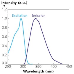
The LED-based biofilm monitor targets, therefore, the natural fluorescence of tryptophan. Tryptophan fluorescence is excited via a numerically optimized sensor head equipped with a UVC LED light source and the fluorescence light collected with optical fiber bundles. The UVC LED light can be switched on and off instantaneously within several milliseconds to yield highly reproducible light intensities while minimizing power consumption.
The scientists calibrated their prototype with tryptophan solutions and two characteristic marine bacteria strains, resulting in a linear signal response, satisfactory background suppression, wide dynamic range, and an experimental detection limit of 4 × 10³ cells/cm2. Successful field experiments were then conducted in the Baltic Sea over a period of 21 days. From the very first adhering bacteria, measurements yielded biofilm's three characteristic phases of formation, concluding with a fully developed biofilm. Though still under development, potential applications for the sensor include shipping, deep sea research and, after further miniaturization, industrial and biomedical industries.
Marine sensors
On the other hand, there are a number of commercially proven, in-service marine sensors with built-in UVC LED-based devices that actually prevent biofouling, greatly enhancing the sensor's productivity.
As previously noted, biofilm growth can begin on coastal and marine sensors within a week of deployment. As a result, the Alliance for Coastal Technologies (Solomons, MD) estimates that biofouling maintenance consumes 50% of annual operating budgets for companies deploying sensors or systems to monitor the ocean's environmental or industrial parameters, including:
- Sensors and cameras for underwater imaging;
- Equipment used for optical communications;
- Optical sensors used to monitor water quality (like oil content in water around drilling platforms);
- Sensors used for conductivity measurements of ocean salinity, pressure sensors that measure ocean depth, and temperature sensors; and
- Acoustic sensors that track ocean currents or marine life.
Active control measures range from mechanical wipers/scrapers to chlorine or bleach injection, whereby the chemical is injected into a chamber to disinfect the instrument in between measurements. Passive measures include antimicrobial coatings and biocides, in which a small amount of chemical is released around the sensor to eliminate bacterial growth.
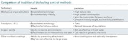
Biofouling on conductivity, temperature, and depth (CDT) sensors—used to calculate salinity, density, sound velocity, and other ocean parameters—can result in drift, lost sensitivity, and response time variations. Most CTD instruments are equipped with wipers and scrapers, which consume relatively more electrical power, are also prone to fouling, and have a high failure rate. Others use copper shutters and chlorine, which also suffer from performance limitations (see table).
As an alternative, some companies have used deep-ultraviolet UVC irradiation, a noncontact, nonchemical solution that can be used across a range of instruments. Radiation in the UVC range prevents biofilm formation by deactivating the DNA in bacteria, viruses, and other microbes. Preventing biofilm formation prevents larger organisms from attaching themselves to the instrument and eventually rendering it inoperable.
Unfortunately, UV radiation also has its limitations. Mercury UV lamps cannot be used in many aquatic settings because of their bulk and high power requirement, as well as the fragility of the lamps and toxic nature of mercury (which can be an environmental issue if a lamp breaks). Mercury lamps are also difficult to start in cold, underwater environments.
On the other hand, LEDs emitting UVC light consume far less power, have a smaller footprint, and deliver the stable, high-intensity light needed for germicidal wavelengths. However, as discussed previously, early UVC LEDs based on sapphire substrates had performance and lifetime issues, and their frequent replacement negated the potential benefits.
Recently, Idronaut (Brugherio, Italy), which designs, manufactures, and supports high-performance oceanographic sensors and instrumentation, has started to deploy the new lattice-matched UVC LEDs in its CTD sensors. The LEDs prevent biofouling by disinfecting a small volume of water surrounding the device, effectively stopping the initial microbe/biofilm growth in its tracks.
The UV dose is based on two factors: the intensity of the light and the length of exposure. Idronaut developed a system that can be custom-configured to optimize the UV irradiation on-off duty cycle on all of its CTD sensors.
By operating in a duty-cycle mode, the LED is programmed to periodically turn on to deactivate the bacterial DNA and then turned off to minimize power consumption (and further improve the LED's lifespan). Since cell division of colonized bacteria and colonization of fouling organisms happens between UV radiation exposures, the cycle can be custom-tuned (depending on the environment) to prevent biofilm formation.
By preventing the biofilm growth at the outset, Idronaut customers are now able to extend the in situ deployment of its CTD sensors, optimizing the instrument's data collection while significantly reducing maintenance costs.
Continued rapid development
Many industries suffer the effects of biofouling, including oil drilling and chemical, food, and pharmaceutical processing. Biofouling adversely affects pipelines, filters, and membranes; catheters, dental equipment, and contact lenses; internal boiler components at power plants; and bioreactors used for drug research.
Considering the high cost of traditional mitigation methods, lattice-matched UVC LED devices represent a new, groundbreaking way to develop more effective and less costly solutions. As a result, further development of LED-based instruments is expected to continue at a rapid pace, resolving chronic issues that have plagued global industries for decades, if not centuries.
REFERENCE
1. M. Fischer, M. Wahl, and G. Friedrichs, Biosens. Bioelectron., 33, 1, 172-178 (Mar. 15, 2012).
About the Author

Hari Venugopalan
Director of Global Product Management
Hari Venugopalan is director of global product management at Crystal IS (Green Island, NY).