Mode-division Multiplexing: On-chip mode-division-multiplexing extends single-fiber communications capacity
JAN MARKUS BAUMANN, KASPER INGERSLEV, YUNHONG DING, and TOSHIO MORIOKA
The amount of data transmitted through the Internet has grown exponentially in the last few decades, driving the need to increase the transmission capacity of optical fibers. To meet the need for higher data rates, many transmission techniques like wavelength-division multiplexing (WDM), higher-order modulation formats, or advanced digital signal processing techniques have been used.
In recent years, space-division multiplexing has attracted much attention and uses additional spatially separated channels to enhance the data capacity on top of WDM, which transmits separated channels at different wavelengths in the same fiber.1 In the simplest case, parallel fibers are a form of space-division multiplexing. However, more interesting and versatile systems use multicore fibers and few-mode fibers (FMFs), where there is potential to integrate functions like amplifiers for all channels at once.
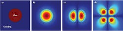
The modes inside a fiber are possible patterns of the electromagnetic field that propagate along the fiber. The so-called linearly polarized (LP) modes are commonly used for multiplexing (see Fig. 1). Because of their orthogonality, they can be used as separate spatial channels and would ideally propagate without coupling, but small perturbations in the refractive index profile of the fiber or bending of the fiber can cause cross-coupling between the channels. Nevertheless, even with strong cross-coupling between channels, they can be used as separate spatial channels by using multiple-input-multiple-output (MIMO) signal processing at the receiver, which can revert the coupling digitally.
To achieve mode-division multiplexing (MDM), multiplexers are needed that can multiplex several data inputs into different modes efficiently. There are several methods of multiplexing and coupling modes into FMFs, like photonic lanterns, multi-plane light conversion, and others.
At the Center for Silicon Photonics for Optical Communication (SPOC) of the Department of Photonics Engineering at the Technical University of Denmark (DTU Fotonik), there has been research on silicon (Si) photonic-integrated-circuit (PIC)-based mode multiplexers that can couple from on-chip waveguides directly into FMFs above the chip.2
While not as efficient in terms of power or crosstalk compared to some other methods, these Si PIC multiplexers have a very small footprint and can be integrated with other on-chip components, making it possible to have whole on-chip MDM transmitters and receivers. The possible low costs and compactness of these couplers suit the needs for transceivers in data centers, where size and cost are a major concern.
Multiplexing on a chip
An on-chip MDM device was designed and fabricated at the DTU National Center for Micro- and Nanofabrication (DTU Danchip). The chosen technology was silicon-on-insulator (SOI), which consists of a thin 250 nm Si layer on top of a several-micron-thick silicon dioxide (SiO2) layer on a whole Si wafer for stability.
Silicon is a transparent material at telecommunications wavelengths and its high-refractive-index contrast to SiO2 allows small on-chip waveguides and tight bends, resulting in high packaging density. Because it is cheaper than other semiconductors and promises the use of mature Si fabrication technologies, SOI has been a focus for integrated optics. Furthermore, co-integration of photonics and electronics on the same chip is possible, enabling more complex on-chip systems.
The function of an on-chip MDM is multiplexing data streams in different waveguides on the chip into different modes of a single few-mode fiber. The data signals are created externally and coupled onto the chip. For coupling onto and off the chip, so-called grating couplers are used.3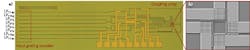
On the chip, the signals from the input are split up and guided to a grating coupler array that consists of four two-dimensional (2D) grating couplers designed to emit light vertically. On the way to the grating coupler array, some phase changes are introduced through small heaters above the waveguides that change the local refractive index just slightly through the thermo-optic effect.
The heaters are tuned before the experiment to create the correct field profiles above the 2D grating array. This means that for the LP01 modes, the signals at the grating couplers must be in phase, while for the LP11 modes, the signals on opposing grating couplers need a phase shift of π to get as close as possible to the correct mode profile of the fiber.
Since everything on the chip is passive, the chip can be used as a multiplexing chip as well as a demultiplexing chip, which demultiplexes the incoming modes of a FMF into different fibers.
Transmission characterization
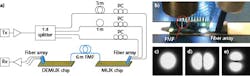
To test the multiplexing and demultiplexing capabilities of the chip, a 1550 nm laser modulates and carries a 16 gigabaud (GBd) quadrature phase-shift keying (QPSK) 32 gigabit per second (Gbit/s) data signal. The signal is split into three paths while short fibers of different length are added in the different paths to decorrelate the data. All the signals are coupled to the grating couplers on the multiplexing chip via a fiber array.
From the chip, the signals are multiplexed into different modes of a few-mode fiber, which is positioned vertically above the array. In this experiment, the signals are coupled into the LP01y, the LP11ay, and the LP11by modes, but could also be coupled into other modes of the other polarization by connecting the signals to the respective inputs of the fiber array.
The FMF used was slightly elliptical so that the patterns would not rotate inside the fiber. After the FMF, the signals are demultiplexed by a chip identical to the multiplexing chip. One output at a time is connected to a coherent receiver and the data is collected by a digital storage oscilloscope and processed offline.
Before characterizing the device and transmitting data, the on-chip heaters are activated on both the multiplexing and demultiplexing chips and the FMF is rotated above the demultiplexing chip to align the mode pattern to the chip. The transmission and crosstalk of three channels is measured over the whole system, from the input fiber array of the multiplexing chip to the fiber array output after the demultiplexing chip.
For the data transmission experiment, the polarization with the highest received power is taken as the transmission channel, due to the random orientation of the polarization to the demultiplexing chip and the lack of its control. The channels have losses between 33 and 38 dB and crosstalk values between the channels ranging from -12 to -20 dB. The whole signal (a pseudo-random bit sequence) was received without any errors. Transmissions over longer distances will be subject to further investigation by our team.
Our demonstrations show that multiplexing can be done directly chip-to-chip. Only three of the possible input channels at the multiplexer are used, because in the setup, the polarization of the arriving signal could not be controlled. Also, a three-channel, 3 × 32 Gbit/s chip-to-chip connection has been demonstrated using the LP01 and LP11 modes in a two-mode FMF. The multiplexing chips are fabricated on an SOI platform making them compatible with many other Si photonic elements.
OAM mode multiplexing
Orbital angular momentum (OAM) modes are another basis for mode multiplexing. These OAM modes are described by their topological charge, L, and their polarization, σ, such that each photon carries an OAM of Lħ (where ħ is the reduced Planck’s constant), and a spin angular momentum of σħ. This means that for each L value there are four orthogonal modes corresponding to two signs of L and σ. In special optical fibers, these modes can be transmitted with minimal coupling.4
In one of our experiments in close collaboration with Boston University, we transmitted 12 different OAM modes simultaneously, each carrying a QPSK signal with several wavelengths—thus exploiting all possible degrees of freedom for data multiplexing. The modes were generated in free space using q-plates, which are half-wave plates with a rotating fast axis.5 This setup takes one circular input polarization and converts it into one OAM mode, such that each q-plate can generate two orthogonal modes.
Using six q-plates combined in five beamsplitters, different shapes of OAM modes were revealed as they interfered with a Gaussian beam (see Fig. 4). The signal was transmitted through a 1.2 km OAM fiber and at the output it was separated by a free-space mode filter before being received in a coherent receiver.6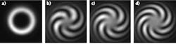
Another research topic at DTU Fotonik is efficient OAM mode multiplexers, possibly on-chip, since creating the modes in free space and combining the beams with different modes via beam splitters is not the most efficient way when looking for higher mode counts and requires a complicated, large setup.
ACKNOWLEDGEMENT
The researchers would like to acknowledge the Center for Silicon Photonics for Optical Communication (SPOC) at DTU Fotonik.
REFERENCES
1. D. J. Richardson et al., Nat. Photonics, 7, 5, 354–362 (2013).
2. Y. Ding et al., “Efficient PIC mode multiplexer using grating coupler array with aluminium mirror for few-mode fiber,” CLEO 2015 paper STh1F.1, San Jose, CA (2015).
3. Y. Ding et al., Opt. Lett., 38, 15, 2732–2734 (2013).
4. P. Gregg, P. Kristensen, and S. Ramachandran, Optica, 2, 3, 267–270 (2015).
5. L. Marrucci, C. Manzo, and D. Paparo, Phys. Rev. Lett., 96, 163905 (2006).
6. K. Ingerslev et al., “12 mode, MIMO-free OAM transmission,” OFC 2017 presentation M2D.1, Los Angeles, CA (Mar. 20, 2017).
Jan Markus Baumann and Kasper Ingerslev are PhD students, Yunhong Ding is senior researcher, and Toshio Morioka is professor, all at the Technical University of Denmark Department of Photonics Engineering (DTU Fotonik), Lyngby, Denmark; e-mail: [email protected]; www.fotonik.dtu.dk.