Motion Control: Starbugs: Piezoelectric robots enable next-generation astronomy
JAMES GILBERT
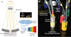
Using fiber optics, today's astronomers can simultaneously observe thousands of celestial objects with a single ground-based telescope (see Fig. 1a), with spectroscopy usually the technique of choice. Several facilities across the globe are conducting large spectroscopic surveys of the sky, recording the optical spectrum of millions of individual stars and galaxies, building huge databases for the next era of astronomical research.
Fiber-fed multi-object spectroscopy has the inherent problem of how to place the fibers at the necessary positions on the telescope's focal surface. One method is to use a "plug-plate," where mounting holes are drilled in a custom mount according to the position of the stars in the sky at a specific time.
Preferably, though, the fibers would be robotically reconfigured in situ. To this end, the Australian Astronomical Observatory (AAO) has developed "Starbugs," which are miniature piezoelectric robots, one per fiber, that essentially give each fiber its own pair of legs. As a result, many hundreds of optical fibers can be independently positioned at a telescope's focus.
Starbug micro-robots
The Starbug (see Fig. 1b) is a discrete-stepping miniature robot specifically developed to enable fast, accurate, high-multiplex fiber positioning across a telescope's focal surface. Starbugs have just three main parts: a piezoceramic tube, held within another piezoceramic tube by a solid ring at one end. The free ends of the tubes are aligned and polished flat, becoming the device's "feet." Starbugs have typical diameters of 6–12 mm.
Deformations that result from applying an electrical potential to electrodes on a Starbug's actuators can be exploited to produce a stepping or "walking" motion (see Fig. 2a). The maximum displacement achieved by each actuator is on the order of 20 μm, meaning that a single Starbug "step" is of a similar magnitude. At a nominal stepping frequency of 100 Hz, this translates to a speed of 2 mm/s. A Starbug's strength, however, lies in the fact that it can take much smaller steps (on the order of 1 μm) when needed. It is this combination of high speed and high accuracy that lends itself so well to astronomical use, where errors of only a few microns are tolerable before the light from your object is lost.
Being low-cost devices, arrays of many Starbugs can be produced. This is the crux of the Starbugs concept, where an entire arrangement of optical fibers can be reconfigured at once (see Fig. 2b).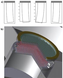
A Starbug's inner piezo tube has four equally spaced electrodes on its outer wall. This means that steps can be made in four orthogonal directions (±x and ±y), depending on which electrodes receive the drive signal. Additionally, spacing electrodes on the outer piezo tube in a certain way enables the rotation of a Starbug about its center. Being able to microstep in x, y, and theta makes Starbugs extremely flexible as positioning devices.
A Starbug's central piezo tube provides a completely clear aperture for the insertion of optical components. Many types of optical component can be mounted within the tube: a single optical fiber, a large fiber bundle, or a microlens assembly, for example. Small mirrors, for directing light rather than accepting it, can also be carried. In fact, absolutely anything of a suitable size and mass can be carried by a Starbug.
Starbugs can be sized for the application at hand. Larger versions are capable of moving larger and heavier payloads. Six, 10, and 12 mm versions have been tested to date (see Fig. 3). Ultimately, this sizing presents a trade-off of maximum speed, maximum load, and minimum spacing (pitch).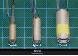
Movement across a smooth horizontal or vertical surface
The relatively small (<20 μm) actuator displacements of a Starbug set a requirement for the smoothness of the surface on which it walks. Low-surface-roughness materials such as glass, plastic, or polished metal are necessary for unimpeded operation. For fiber-optics use, glass surfaces can actually be preferable. An "inverted hanging" format has been adopted for astronomical use, so that fibers and electrical wiring do not obstruct the incoming light. Starbugs can also move on curved surfaces if their feet are polished to match the curvature. This is necessary if a telescope has a spherical focal surface instead of a flat focal plane. Gentle curves (radius ~2 m or more) can be accommodated without re-shaping the Starbug's feet at all.
A force is required to hold Starbugs against the surface on which they move. If the surface is magnetic, then this can be achieved by placing a magnet within or around the Starbug. If the surface is not magnetic, then a vacuum is used to provide the attractive force. The vacuum is created in the volume between the Starbug's two piezo tubes, which is connected to an evacuated chamber with a thin hose.
The ability to position on inclined surfaces is essential for use on a moving telescope. Starbugs can walk at any angle, with only small losses in efficiency due to the gravity vector, even when walking vertically.
A modular control system
A closed-loop control system is used to position all Starbugs in parallel. The Starbugs are tracked in real-time via one or more machine-vision cameras that image the entire positioning area at video rate. A simple calibration routine, performed once, determines the expected step size of the Starbugs in each movement direction and accounts for any variation in behavior between devices.
The Starbugs each have three illuminated markers on their body, arranged in an asymmetric pattern to provide unambiguous position information. The software uses centroid algorithms and averaging to obtain subpixel coordinates for every Starbug and therefore the precise location of all optical faces. On a telescope, these positions would then be mapped to the sky.
The electronics system provides Starbugs with electrical signals according to the distance and direction they must move. Each Starbug requires four sinusoidal waveforms with amplitudes of up to 200 V, although these are shared among multiple devices to reduce the size of the electronics system. Waveforms for hundreds of Starbugs can be generated by a single microcontroller. These waveforms are amplified by high-voltage op-amps and then routed to the Starbug actuators using an array of switches.
The Starbugs' control architecture is inherently modular and easily scalable. While the system has been designed with a few hundred Starbug devices in mind, it is feasible to extend the system to many thousands. The only caveat is that limitations must, at some point, be imposed on the maximum distance a single Starbug is allowed to travel. This is both a physical limitation and a practical one: fiber and wiring lengths are finite, and entanglement and collisions must be managed. The simple solution is to divide the whole system into self-contained subgroups with dedicated metrology and control computers for each.
Performance
The size of a Starbug's step is proportional to the amplitude of the waveform applied to its inner piezo tube (see Fig. 4a). A Starbug's minimum achievable step size defines its positioning resolution. Step sizes of <4 μm are readily achievable. Repeatable submicron positioning has been demonstrated, but has a lower tolerance of alignment errors during assembly. When rotating, Starbugs have a typical minimum angular step size of ~3 arcmins.
For a given step size, how fast a Starbug moves is set by the frequency of the drive waveforms. Testing has shown that the actual relationship between drive frequency and Starbug speed is somewhat dependent on the Starbug design (see Fig. 4b). This is due to resonant modes within the Starbug itself. With angular speed, there is a good linear relationship with frequency and a maximum value of 56 deg/s for the tested device.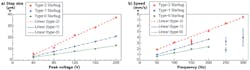
A two-stage approach has been adopted for positioning Starbugs: the first stage uses a high frequency and the maximum step size to position a Starbug near its target as quickly as possible; the second stage then uses a lower frequency and a reduced step size to position the Starbug precisely on its target.
Fixed "patrol radii" are enforced for each Starbug, to simplify target-allocation algorithms and minimize collision-avoidance overheads. An example radius value (part of a real instrument design) is around 100 mm. The diameter of the entire positioning field in this case is more than 1 m, which is typical for the next generation of Earth-based telescopes. Full-field reconfiguration times of less than three minutes are anticipated for such telescopes. This is far beyond the capabilities of other micropositioning systems.
Naturally, Starbugs are not limited to use in astronomy. As a complete system, Starbug positioners are adaptable to any situation requiring fast and accurate positioning of many objects simultaneously. As a single device, the Starbug is a simple and low-cost discrete-stepping motor capable of translating and rotating relative to any flat face.
The future of Starbug technology
Recent Starbug development has focused on their suitability for manufacture in large volumes. This is in preparation for a fully functional telescope instrument called "TAIPAN," due to see first light at Siding Spring Observatory in Australia in 2016. This system will use 150 Starbug devices across a ~400 mm focal surface.
Starbugs are ultimately destined for a place on the largest telescopes of the next generation. One in particular, the Giant Magellan Telescope, will have a 25 m diameter primary mirror and a ~1.3 m focal surface upon which 500 Starbugs will be catching photons.
James Gilbert is an electronics engineer at the Australian Astronomical Observatory in Sydney, Australia; e-mail: [email protected]; www.aao.gov.au.