Contamination Control: Improve yield and quality by monitoring particle contamination during optics manufacturing
JOHN DAVIS
Similar to the way the semiconductor industry has evolved over the past few decades—with wafer processing being performed in ever-cleaner conditions—advanced optics manufacturing is now requiring much cleaner processing environments than were necessary in the past.
Product quality can be compromised through component exposure to particulate contamination. Smaller device structures, use of shorter wavelengths, and higher laser power densities are all factors that make advanced components more susceptible to damage from particle contamination. The first steps toward cleaner process environments are understanding what impact particle contamination can have on production yields and determining the origin of the particle contamination.
Effects on production yields
The optics market encompasses many segments traditionally concerned with particle contamination to different levels. At one end is semiconductor lithography, where particle contamination has been a concern for many decades. Particles on masks and reticles can cause yield defects directly on the end products by blocking the laser beam used to pattern a semiconductor wafer.
More recently, laser optics and assemblies for display systems, machining, and medical applications have caused concern about particle contamination as the laser power densities have increased and wavelengths decreased. Particles below or in thin-film optical coatings can affect adhesion and significantly reduce the achievable laser-induced damage threshold (LIDT). Particles on laser optical assemblies can cause premature laser failure (see table).
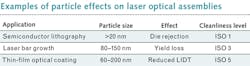
Significant yield reductions can be caused by particles as small as 60 nm, depending on the optical applications. The active layer in a solid-state laser bar is 80–150 nm thick. A particle this size below or in the active layer can destroy the device and impact performance on adjacent devices. This adjacent loss is frequently caused by film stresses in the grown layers caused by the particle.
Particles as small as 200 nm on laser optic substrates can cause defects of 2.3 μm in a standard 1064-nm-wavelength, high-reflector coating.1 Defects of this size can significantly reduce the achievable LIDT.2 Customer feedback indicates that a good rule of thumb is that any particle the size of a quarter-wave layer thickness will negatively impact thin-film coating performance. In a 532 nm wavelength coating, the thickness value can be between 60 and 100 nm, depending on the coating material.
Particle monitoring steps
Particle control methods in laser optics manufacturing vary depending on the manufacturing process step, but mainly fall into three categories: ultrasonic liquid cleaning lines, cleanroom or clean hood systems, and tool maintenance. After grinding and polishing, a laser lens must be cleaned of all residual particles before it can be coated with an antireflection (AR), high-reflection (HR), or filter coating. Typically, a computer-controlled array of ultrasonic baths is used, which consist of overflowing liquid baths that are re-circulated through a filtration system to maintain cleanliness levels.
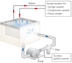
Even though a filtration system is used, it is important to monitor the particle levels in these ultrasonic baths to confirm system performance, and allow data-driven decisions regarding cleaning process optimization and outgoing part cleanliness. Particles can be monitored by either sampling the fluid from the ultrasonic bath with a sampling particle counter or by continuously measuring them in the re-circulation system with an inline particle counting solution (see Fig. 1).
Monitoring the ultrasonic baths over a few weeks should provide enough data to establish statistical process control alarm levels to support data-driven decisions about the cleaning process (see Fig. 2). An alarm at the high end is created to inform when parts put into the cleaning bath shed too many particles and should be re-cleaned for another cycle before moving forward in the manufacturing process. An alarm is also set to indicate that the ultrasonic bath has recovered in cleanliness before introducing the next batch of parts for cleaning. This allows for part cleanliness consistency to be maintained.3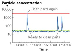
Once cleanliness of parts has been established, parts are typically dried. This should be done with filtered, clean dry air (CDA) or nitrogen—avoid drying stations with heating elements or fans. Both of these devices tend to create and shed particles that will deposit on any newly cleaned parts.
After a cleaning line, it is important to minimize particles from getting on the product surfaces during storage, fixturing, coating, assembly, and inspection process steps. In general, this is controlled by executing these steps in a cleanroom environment or, at a minimum, a clean bench environment. Even in a cleanroom environment, there are many particle sources that can contaminate the product—the greatest particle generators being people. Human-generated particles are minimized with cleanroom clothing, gloves, and protocols, but particles cannot be eliminated.
Air particle monitoring along the manufacturing process steps will quantify how clean and controlled the manufacturing environment is. Particle contamination excursions, either continuous or periodic, can be localized to support rapid elimination, thereby improving the overall quality consistency of the manufacturing environment and reducing particle contamination on manufactured products.
Multiple options exist for monitoring airborne particles in the manufacturing environment, including portable solutions that can be used for periodic monitoring at various locations and troubleshooting as particle excursion events are realized. This solution is typically the first step in particle monitoring for companies new to this quality control method. More advanced particle monitoring is done with small, permanently mounted solutions, which provide continuous monitoring using a variety of particle counters in critical manufacturing areas (see Fig. 3).
Since the laser optics industry does not have a standardized size or shape of substrate, almost all fixturing before optical coating is done manually. This direct human contact exposes the parts to particles that can deposit on the substrate surface prior to coating. As we have noted, even small particles on a substrate surface can create large defects after coating.
To minimize particle exposure during fixturing, ensure that workers are wearing low-particle gloves and other low-particle cleanroom garments. The effectiveness of these controls in addition to the fixturing methods can be confirmed by monitoring for particles with an aerosol particle counter as close to the fixturing location of the parts as possible.
Particle ejection from coating material buildup in thin-film coating systems is a typical particle source to affect yield. Yield impact can be minimized by periodic cleaning of the deposition chamber. Particle monitoring between maintenance cycles can provide data about how dirty the deposition chamber is over time. Applicable data can be collected by using a particle monitor probe to scan around the deposition chamber, determining where the highest particle-generating surfaces are. This data can then be used to optimize maintenance cycles and procedures, or improve the system design of shields and liners to minimize particle generation.
After coating, most laser optics then proceed to inspection and assembly. Particle monitoring and control is required in these areas to minimize particles in bonded layers or on surfaces. These particles cause scattering points, degrading beam quality and, in a worst-case scenario, causing premature laser failures in the field.
Comprehending particle monitoring's importance
To understand the importance of monitoring and controlling particle contamination, consider this example of an inspection station within an ISO class 5 cleanroom during a typical production day (see Fig. 4). There are no particles being measured in the off-production hours when no one is in the cleanroom. As soon as the production shift arrives, the particle levels increase—and this continues to the end of the shift. The data also indicate a number of very high spikes in particle levels during the day. By correlating this data to activities in the cleanroom, it was possible to track down the source of these particles and mitigate the situation.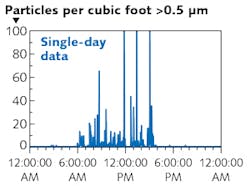
In this case, the monitoring point was located at an optical inspection station that included a high-power fiber light. The high particle counts correlated directly to times when the fiber lights were turned on. When the light's cooling fan turned on, it ejected a large number of particles. After cleaning and replacement of the fans on the fiber lights, the high particle spikes disappeared and production parts were exposed to much lower levels of particle contamination during this inspection step.
Particle monitoring provides the information necessary to make data-driven decisions for optimizing and maintaining advanced quality control in optics manufacturing. The more thoroughly understood the particle contamination sources are, the more effectively they can be reduced and controlled, minimizing product exposure to potential performance-degrading contamination in the process. This is the first step in improving manufacturing processes to meet the increasing yield and device performance levels required as smaller device structures, shorter wavelengths, and higher laser power densities are employed within the industry.
REFERENCES
1. M. R. Kozlowski and R. Chow, "The role of defects in laser damage of multilayer coatings," Proc. SPIE, 2114, 640–649 (1993).
2. S. Richman et al., "Adaptive characterization of laser damage from sparse defects," Proc. SPIE, 9237, 923718 (2014).
3. B. Knollenberg, "Real-time statistical process control of aqueous cleaning systems through in-situ monitoring," Datatech, 3 (Sept. 1999).
John Davis is global applications engineering manager at Particle Measuring Systems, Boulder, CO; e-mail: [email protected]; http://www.pmeasuring.com.