Test & Measurement: Machine positioning uncertainty with laser interferometer feedback
WILLIAM S. LAND II
Laser interferometers are used as a measurement reference for machine correction and accuracy validation in the production of many high-precision motion systems. Under controlled environmental conditions, laser interferometer measurement can provide low measurement uncertainty relative to the achievable accuracy of most commonly used motion control devices.
As such, when processes require the utmost precision, laser interferometer measurement near the machine's work point is frequently used as the feedback mechanism for machine control. In these instances, the use of laser interferometry to characterize the machine's motion is unjustified because the measurement uncertainty of the metrology system is equivalent or higher than the motion error. The accuracy of the motion of these machines must be equated to an uncertainty in the feedback system's measurement of the defined work point's motion.
This article is not meant to be an introduction to measurement uncertainty, laser interferometer feedback, error/uncertainty budgeting, or rigid body error motions. Instead, it is an overview of the level of work-point position measurement uncertainty that can be obtained in a specific machine design.
Uncertainty in laser feedback systems
The environment of the laser is the chief concern when using interferometric feedback. The wavelength of light, which is used as the link to the base metric of motion—the meter—varies as a function of the refractive index of the medium through which it is passing. In air, the index of refraction varies significantly with changes in temperature, pressure, humidity, and even the local composition of the air. As a result, accurate positioning measurement requires continuous and accurate knowledge of these environmental parameters for use in active wavelength compensation. Additionally, the rate and type of air flow over the laser beam will cause local fluctuations in refractive index, resulting in what is seen as measurement noise.
In addition to environment-related contributors, other influences on the combined uncertainty of machine motion include several elements. The flatness and alignment of the plane mirror optics used in the interferometry system contribute to the uncertainty in the motion of the work point. Likewise, the effects of angular error motions over any small Abbe offset present between the interferometers and the defined work point can be a major contributor. Finally, as in almost all precision machines, the thermal expansion of any number of components over an uncompensated distance will introduce significant uncertainty in the control of the work point's motion.
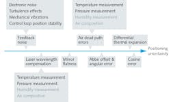
Figure 1 is a diagram of the major uncertainty contributors to motion control in machines where homodyne laser interferometer feedback is used near the work point. The ability to understand and minimize these influences on a specific measurement is critical to achieving ultra-precise motion in such systems.
Quantifying positioning uncertainty
The impact of the uncertainty contributors outlined in Fig. 1 is a function of each machine's design, length of travel, environment, and defined work point. Quantification can only be estimated on a case-by-case basis where machine specifics are known. Each machine design must have its own uncertainty analysis, even if similar to previously analyzed machines. Therefore, we present the motion of a machine vision inspection station used as a metrology tool at the Aerotech headquarters as a specific example in measurement uncertainty estimation.
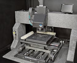
The inspection station (see Fig. 2) has been designed with a large payload plate that not only carries a vacuum chuck for substrate retention, but also two-plane mirror reflectors for use in laser interferometer feedback at the work point. When evaluating the uncertainty in the measurement of work point motion by the lasers, this machine shares all of the major contributors outlined in Fig. 1. By working through these sources one by one, a reasonable estimate of measurement uncertainty can be obtained for this particular machine's application.
As in all engineering tasks, certain assumptions must be made in the quantification of uncertainty, and their validity is dictated by the uncertainty or error budget trying to be achieved for a given application. For example, the interferometer's uncertainty is being neglected in this case, as it is assumed insignificant to the resulting measurement uncertainty. This application-specific depth of analysis is another important reason why each machine design and, more specifically, machine task should have its own uncertainty analysis.
Resolution and feedback noise
The feedback noise floor dictates the minimum effective resolution of the machine, and also sets a floor for the uncertainty in measuring the work point's planar motion. As shown in Fig. 1, the feedback noise in this case is dominated by electronic noise, mechanical vibration, control-loop stability, and, most influentially, air turbulence across the open interferometer beams. In this machine, the influence of mechanical vibration on the interferometers is minimized through the use of a high-compliance, passive air isolation system.
Likewise, the coordinate measuring machine (CMM) itself is surrounded by an environmental enclosure to minimize air currents across the laser beams. The overall implementation of this machine produces long-term (>3 hours) laser stability of approximately 25 nm root-mean-square. Additionally, this machine utilizes Renishaw RLD double-pass plane mirror interferometers that have a digital measurement resolution of 10 nm, which is assumed to be a square distribution width.
Laser wavelength compensation and dead path errors
The need for compensation of wavelength change as a function of the local environment of the laser has been long documented,1 and is an automated feature in most commercially available interferometer systems. In this case, humidity and air composition changes are small enough to neglect. However, the accuracy/uncertainty of wavelength compensation, and therefore the interferometric measurement itself, is dictated by the ability to accurately measure changes in the remaining environmental parameters of temperature and pressure.
When applied to distance measurement, as in this machine, interferometric measurement is performed relative to some reference location. As a result, wavelength compensation is only actively applied to the number of fringes, or waves, counted by the detector in a relative move away from the reference location.
In practice, the laser heads cannot be placed in contact with the mirrors when at the reference location, where some relief must be provided. There is always a small portion of laser beam that is not accounted for in the wavelength compensation. When the local environment changes, this length of beam is uncompensated and causes small shifts in the system's zero location.
This is known as dead path error. Because the errors contributed from omitted wavelength compensation are length-dependent, minimizing the amount of space between each laser head and the location of the mirrors at the reference point will minimize induced uncertainty from dead path errors.
Both laser wavelength compensation and dead path effects on uncertainty in the measurement of the work point are length-dependent. As such, their influence over the greatest operating distance will be considered for this quantification example. The weather station used to correct for environmentally related wavelength changes in this machine has an absolute temperature accuracy of 0.2°C and an absolute pressure accuracy of 1 mbar. The relative change of temperature and pressure over a 3-hour test, which affects dead path error, has been observed to be less than 0.1°C and 0.5 mbar, respectively.
For the sake of simplicity, the impacts of these values on measurement uncertainty can be quantified via the most recent laser scale correction sensitivity coefficients per ASME standards.2,3 This avoids the need to perform propagation of uncertainty analysis per the Guide to the Expression of Uncertainty in Measurement (GUM),4 and the corrected Edlén equations.5 Assuming machine operation around standard temperature, pressure, and humidity, the uncertainty contribution of the weather station's temperature and pressure measurement accuracy is 29 nm and 5 nm, respectively, over the full 300 mm travel of the machine.
Likewise, the relative change in temperature and pressure during a given test contributes 5 nm and 1 nm of measurement uncertainty, respectively, over the 96 mm of dead path per axis. These contributions are all considered to be square distribution widths. A more thorough explanation of both laser wavelength compensation and dead path errors can be found in Renishaw technical paper TE3296.
Mirror flatness, orthogonality, and cosine errors
Compared to the implications of laser wavelength changes, the effects of mirror flatness and mechanical alignment on measurement uncertainty are more straightforward. The flatness of each mirror directly constitutes positioning uncertainty of the work point in the form of straightness errors. Additionally, the alignment of the mirrors' surface normals to the defined XY coordinate plane will induce cosine errors in the definition of the X and Y axis scales. Likewise, but independent of the mirrors' alignment, is the induced cosine error from the alignment of the laser beams to each mirror normal. Finally, orthogonality of the mirror surfaces to each other will impart a squareness error on the position measurement of the work point.
The mirrors used in this machine are specified to have 63 nm of peak-to-valley flatness over their full area with a 95% confidence interval in this specification's validation report. Through mechanical fixturing and machine tolerancing, the alignment of the mirror normals to the XY coordinate plane is <25 μrad, and the alignment of the laser beams to the mirrors is also <25 μrad per the level of signal variation observed through travel. Finally, the orthogonality of the two mirrors to each other is software-corrected via a square reference artifact and reversal technique. Uncertainty in the reversal corresponds to a <.05 μrad squareness error between the mirrors.
Therefore, the mirror flatness specification contributes 16 nm of measurement uncertainty. The cosine error of both mirror and laser alignment contributes 0.1 nm each over the machine's full travel. The orthogonality of the two mirrors will also contribute 15 nm of a triangular uncertainty distribution over the machine's range.
Abbe offset and angular error
The effects of angular error motions on the measurement uncertainty of a work-point position are often some of the most substantial. This is because of the frequency of including Abbe offsets between the measurement point and the defined work point of interest. One of the primary reasons for using interferometric feedback at or near the work point is to eliminate Abbe offset, and thereby eliminate the effects of angular error motions on work point measurement.
In this particular example, there is nominally zero Abbe offset between the positioning of the laser beams, the feedback mechanism, and the defined work point. Therefore, there is a negligible amount of measurement uncertainty contributed by the angular error motions of the bearing ways.
Differential thermal expansion of machine components
Lastly, the differential thermal expansion of various machine components can have a drastic impact on measurement uncertainty. For example, because of the work point's definition in this machine, there is a large length of granite between each laser head and the work point that is left to expand and contract freely with changing temperature.
If the temperature of the granite machine base would change during a test, the granite bridge holding the camera would expand or contract, moving the optical axis relative to the laser heads. In this case, the feedback control of the interferometer system would maintain the same distance between each mirror and each laser head. This would cause the work point to shift without seeing a change in position reading, and would therefore contribute to the measurement uncertainty over the course of a measurement.
In this particular machine design, however, there is also a lesser length of aluminum between the mirror faces and the work point, in the form of the payload plate, left to expand and contract with temperature change. By design, the lengths of granite and aluminum contribute opposite directions of work-point motion relative to a position being measured on a grid plate when both expand and contract.
Therefore, as long as the ratio of the respective lengths of aluminum and granite are equivalent to the ratio of their respective coefficients of thermal expansion, the growth of each machine component contributes a negligible amount of measurement uncertainty to the measurement of a part under test.
Expanded standard uncertainty
When combining the uncertainty contributions of uncorrelated inputs, it is possible to sum the estimated uncertainty of their distributions in quadrature. This is a simplified application of the propagation of uncertainty described in the GUM,4 and is valid for this example.
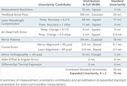
The table shows a summary of the major contributors considered in this analysis, their uncertainty contributions, and the combined and expanded uncertainty contained in the system's positioning measurement. Uncertainty summaries such as this table can give insight into where efforts should be focused to further improve measurement.
It is important to note that there have been numerous assumptions made throughout this uncertainty analysis. Likewise, there is a mass of underlying principles and background knowledge that has been used to guide this analysis. Thus, each machine design should be accompanied by its own uncertainty budget and analysis.
The major contributors outlined in Fig. 1 may not always be sufficiently exhaustive for other cases, nor the simplifying assumptions made throughout appropriate for lower levels of desired measurement uncertainty. To achieve a better understanding of measurement uncertainty and its estimation, a good reference is the Guide to the Expression of Uncertainty in Measurement (GUM) and its supplementary materials,4 available for free at the International Bureau of Weights and Measures' website.7
REFERENCES
1. B. Edlén, Metrologia, 2, 71–80 (1966).
2. ASME B5.57. – "Methods for performance evaluation of computer numerically controlled lathes and turning centers," American Society of Mechanical Engineers, New York, NY (1998).
3. ASME B89.1.8. – "Performance evaluation of displacement measuring laser interferometers," American Society of Mechanical Engineers, New York, NY (1998).
4. See http://www.bipm.org/en/publications/guides/gum.html.
5. K. P. Birch and M. J. Downs, Metrologia, 31, 4, 315 (1994).
6. M. V. Chapman, "TE329: Environmental compensation of linear laser interferometer readings," Renishaw technical white paper.
7. See http://www.bipm.org/en/publications/guides.
William S. Land II is product application engineer at Aerotech, Pittsburgh, PA; e-mail: [email protected]; www.aerotech.com.