Positioning equipment - the challenge of building a solid foundation for optics
Positioning and stabilizing optics may seem a humble task, but it paid off in a big way for Albert A. Michelson in 1907, when he received the Nobel Prize in Physics "for his optical precision instruments and the spectroscopic and metrological investigations carried out with their aid."
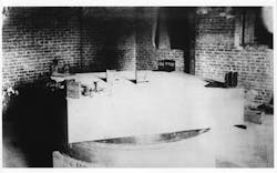
His most famous experiment was an 1887 attempt with Edward Morley to measure how the Earth's motion affected the speed of light. The measurement required exacting precision, so they assembled a multi-pass Michelson interferometer on a foot-thick slab of sandstone measuring 5 ft2 that floated on liquid mercury in the basement of a massive stone building to isolate it from thermal variations and vibrations from passing horse traffic (see Fig. 1). They could detect shifts as small as 1% of a fringe—but they failed to find the ether drift predicted by classical physics, and thus helped launch modern physics.
Holography demands stability
Early laser experiments didn't require such extreme stability, and typically were performed on laboratory tables. Ordinary optical measurements were made on optical benches, essentially long, straight rails holding optical mounts to align a series of lenses.
The first issue of Laser Focus in January 1, 1965 didn't mention tables, mounts, or other positioning equipment. But it did include a lengthy report on the then-new subject of three-dimensional (3D) laser holography. We noted that recording holograms with then-available continuous-wave (CW) lasers required long exposures. During that time, we wrote, "the reflecting objects must remain stationary to less than about 1/8 wavelength of the illumination of the exposure." To achieve that high stability, Emmett Leith and Juris Upatnieks had to fill the HO-gauge toy train engine in their iconic hologram with epoxy and glue it to the tracks (see Fig. 2).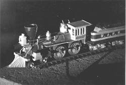
"Before holography, you never had to worry about the stability of the tabletop," recalls Milton Chang, who earned a PhD for holographic research at Caltech under Nicholas George. He and fellow grad student John Matthews worked on a homemade optical bench made by floating a massive steel plate on a pair of heavy-duty truck inner tubes.
I spent the summer after my junior year working in that lab, and was quite impressed by the setup. But it didn't provide the several minutes of absolute stillness needed for serious holography. The lab was on the first floor, so it picked up vibrations when the elevator went up and down, and from passing traffic. The only way to record good holograms was in the middle of the night, when no one else was in the building and the elevator slept.
After he graduated, Matthews set out to develop better optical tables for holography. He and Dennis Terry, a supervisor in the Caltech machine shop, decided to form their own company while spending a day at Newport Beach in 1969. The name Newport Research was inspired by the beach and their interest in the scientific market. Matthews developed ways to damp vibrations in the tables, and adapted a honeycomb structure used in aerospace for its rigidity and light weight. They earned $46,000 in their first year working in a garage, and then moved into a shop in nearby Fountain Valley. Chang joined them in 1972 as marketing manager.
Artists making holograms took a low-end approach to vibration isolation. In 1970, Canadian artist Jerry Pethick and laser physicist and holographer Lloyd Cross stuck plastic pipes and concrete blocks into a box filled with sand, and attached optics to them with C clamps. Soon, holographic art was emerging from basement holographic sandboxes.
A foundation for lasers
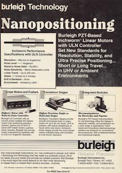
Optical positioning equipment had become an important business by the time of our January 1975 issue. Newport ran a full-page ad dense with information in small type, many photos, and two graphs of vibration isolation and damping. They had plenty of competition. Information-rich ads from Aerotech (Pittsburgh, PA; see Fig. 3) and Burleigh Instruments (East Rochester, NY) described "optical erector sets" for holding components. Modern Optics (El Monte, CA) advertised optical tables starting at $1000 and precision mirror mounts for $49. And Scientech (Boulder, CO) offered magnesium-alloy optical benches for $100 per meter in lengths to 5 m.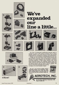
Another new application emerged in the early 1980s. Mayhew visited a mysterious southern California customer called WED Enterprises to make measurements for a new optical table—and found the WED stood for Walt E. Disney. The optical tables were replacing an assembly of 4 × 4 boards floating on inner tubes in creating special effects for movies like Tron.
Robotics and programmable positioners
The 1980s brought numerical control to positioning equipment for optics and to industrial laser systems. "The first U.S. industrial laser robot system was installed in 1984. By 1989, industry sources predict that several hundred laser robot systems could be in place performing spot welding and cutting operations," wrote David Belforte in our October 1984 issue.
Flipping through the rest of that issue showed the emerging trend. An ad from Oriel Corp. (Stratford, CT) mentioned computer-compatible stepping motors and drives with active control to maintain constant speed for motorized micropositioners, and Newport advertised a motorized drive with a keypad control. Our products section described a positioning system that Anorad (Hauppauge, NY) had developed for automated laser drilling and cutting of printed-circuit boards.
Nanotechnology and mountaintop optical tables
Our editorial coverage of positioning equipment expanded in the 1990s. A feature in our January 1995 issue (see Fig. 6) listed options for table surfaces that still sound familiar. "Stainless steel is by far the most common top-skin material because steel has a high stiffness-to-weight ratio and can be laminated, machined, drilled and tapped, then damped with reasonable effort," wrote Jerry Hobbs. Aluminum skins are light and easy to machine, but are more prone to deformation and contamination. Granite can be polished flatter, but it is more massive and amplifies a broader range of vibrations.
The late 1990s also saw optical tables reaching new heights at the Keck Observatory on Mauna Kea, Hawaii. Newport supplied more than 50 tables for an optical delay line used for interferometry with the twin 10 m telescopes. Getting the tables up the mountain was a picnic compared to installing and testing them in the thin air at 14,000 ft, recalls Warren Booth, a senior manufacturing engineer at Newport.
The age of nanopositioning
A March 2004 feature (see Fig. 8) by Steve Kidd of Melles Griot UK and two colleagues from LNL Optenia (Ottawa, ON, Canada) described a six-axis stage with active alignment that could align a probe to a 2 μm waveguide with 10 nm resolution within a second or two. That marked a dramatic advance over the 10 minutes needed manually. An ad from Mad City Labs (Madison, WI) offered nanopositioning systems with subnanometer precision.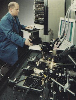
New cutting-edge research required new positioning techniques. Exacting precision was needed to prevent any relative motion between the ultrashort laser and the acceleration chamber in the Berkeley Laboratory Laser Accelerator (BELLA) at the Lawrence Berkeley Laboratory in California, which we described in June 2013. That required tuning vibration damping of the optical tables at the site rather than in the factory for the first time ever, says Booth of Newport.
Vibration isolation is finding applications far beyond optics. The oddest Booth recalls was at a biotechnology company trying to produce genetically engineered rats. The rodents were so finicky that they wouldn't breed if they could feel any vibration, and the company was near active train tracks. The baby rat population boomed after he installed an isolation table as a foundation for a rat housing project. (Booth called it a "rat brothel," but somebody might find that offensive.)
Looking forward
One emerging trend is the "smart table," with a control system that actively identifies resonant frequencies and damps them with faster settling time than standard tables. "Some semiconductor companies are looking for that now, as a way to improve throughput," says James Fisher, vice president for optical components and vibration control at Newport, which recently introduced one. Figure 9, from our March 2015 issue, shows how that system improved the quality of nanostructures fabricated by Steven Koo at MIT in a fifth-floor laboratory.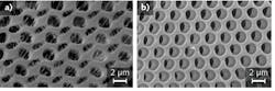
So far, the market for active systems has been limited to the most sensitive equipment, including atomic force and scanning-probe microscopes as well as semiconductor fabrication. But Fisher says active systems will become more affordable as sensor costs drop and electronics become more powerful, and "people will need more active systems" as their demands for extreme stability and precision increase.
New technology offers other options. The same March 2015 feature described totally passive negative-stiffness vibration isolators developed by Minus K Technology (Inglewood, CA). Based on a combination of coiled springs and negative-stiffness flexures, they have a low natural frequency of 0.5 Hz, making them more effective at such low frequencies than air or active damping, says Steve Valma, operations manager at Minus K. They don't require an air supply or power. They are finding growing applications as sensitive instruments have become small enough to be installed on higher floors, where they are more vulnerable to low-frequency building vibrations. One recent inquiry came from a person in the 20th floor of a Hong Kong building who was having problems making measurements with an atomic force microscope.
Valma says the passive negative-stiffness isolators can be made on a wide range of scales. NASA's Johnson Space Flight Center is using six custom-made isolators with capacity of 10,000 pounds each to test the James Webb Space Telescope on the ground. On the other end of the scale, their smallest units can handle 25 pounds each. Their most interesting application so far has been to isolate the high-end Döhmann Helix 1 audio turntable just introduced by Audio Union. At $40,000, the turntable is designed for serious audiophiles who are very affluent-a far cry from a stable table to coddle fussy rats.
About the Author

Jeff Hecht
Contributing Editor
Jeff Hecht is a regular contributing editor to Laser Focus World and has been covering the laser industry for 35 years. A prolific book author, Jeff's published works include “Understanding Fiber Optics,” “Understanding Lasers,” “The Laser Guidebook,” and “Beam Weapons: The Next Arms Race.” He also has written books on the histories of lasers and fiber optics, including “City of Light: The Story of Fiber Optics,” and “Beam: The Race to Make the Laser.” Find out more at jeffhecht.com.