Novel Detectors: SiC bolometer laser power sensor has advanced specs
A laser-power meter (LPM) that uses a volume absorbing, single-crystal, silicon carbide (SiC) bolometer and detects wavelengths from 190 nm to 200 μm has been developed at Firebird Sensors (Reno, NV). Attributes of SiC that are important for LPM sensing include wide spectral range, high thermal conductivity (5.1 W/cm·K), and high binding energy (4.67 eV). In addition, the SiC sensor lacks mechanisms that cause drift: there is no diffusion of impurities within the SiC up to temperatures >1200°C; there are no grain boundaries; and the electrode structure is stable above 800°C.
In conjunction with heat-sink integration, these SiC attributes yield characteristics that include a dynamic range of 106 (1 mW to 1 kW), no fan or water-cooling requirement to measure powers >1 kW, exceptionally high damage threshold (undamaged by peak pulse powers of 10 TW/cm2), high accuracy (±0.1% at full scale), and short time between measurement cycles (~1 s).
Two configurations
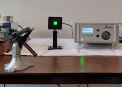
The meter head (MH) includes a sensor and an aluminum heat sink (see figure). A detachable handle located on top of the MH is not shown. The so-called “MEGA” MH has two configurations of operation: sensor-sinked or sensor-isolated. The fast-response (FR) MH is in sinked configuration only.
The sinked configuration minimizes response time but requires that a pulsed laser emit at a pulse rate of 10 Hz or more to give a steady average power reading. The isolated configuration maximizes low-power sensitivity and can measure the average power emitted from a pulsed laser at frequencies down to 2 Hz.
In the sinked configuration, heat is rapidly transferred from the sensor to the heat sink, lowering the sensor’s natural 100% response time to below 6 s. In the isolated configuration, the sensor heat loss to the heat sink is minimized; this extends the low frequency and low power range by an order of magnitude, but increases the natural 100% response time to about 30 s.
In each configuration, the MEGA and FR MHs can be used with or without a concave focusing mirror. The purpose of the mirror is to further extend the low-power range by increasing the amount of laser radiation absorbed by the sensor. The sensor’s absorption is a function of wavelength and, to some degree, of temperature.
At wavelength values below and above 10.6 μm, part of the laser radiation passes through the sensor. The sensor surfaces are roughened to disperse reflected and transmitted beams; however, a heat dump should be located behind the sensor when high powers are being measured or when a mirror is not used. At or near a 10.6 μm wavelength, SiC exhibits the Restrahlen effect, where nearly 100% of the radiation is absorbed near the surface, then nearly 100% of the absorbed radiation is re-emitted from the surface. In this case, the sensor surface should be misoriented from the laser by 5° to 10°, and a heat dump should be placed in the path of the reflected beam.
The sensor’s dynamic range of 106 is achieved by a combination of sensor configuration, adding the mirror when needed, and maximizing the operating-temperature range by heat-sinking. The minimum power measurement capability is obtained by isolating the sensor and using the mirror to maximize sensor absorption.
The maximum continuously measurable power at a given wavelength is dictated by the operating-temperature range, which depends on the sensor and heat-sink sizes—high power can be measured in both sinked and isolated configurations. In the sinked configuration, the maximum measurable power is the power that raises the heat-sink temperature to 200°C (due to a temperature limit dictated by circuitry inside the MH). To date, we have determined that a 17 mm sensor in a 76.2 × 76.2 × 32.3 mm FR heat sink can measure up to 2 kW of continuous-wave radiation at a 1 μm wavelength. In the isolated configuration, the maximum measurable power is the power that raises the sensor temperature to 800°C.
Damage threshold (DT) at a given wavelength is a function of both the average power in a laser beam cross-section and the peak pulse power, where, although the average power may be well below the DT of a LPM sensor, the peak pulse power may still damage the sensor. In both cases, as the average power in a laser beam increases, the DT of the sensor decreases.
Experimental results
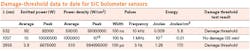
To date we have measured DT at three wavelength (λ) values (see table). DT was reached in two of the three tests, while in the third test, the SiC sensor was not damaged. In all three tests, the damage threshold exceeded that of any other LPM sensor by many orders of magnitude.
A unique capability of the FR MH is its ~1 s waiting times between measurement cycles. This is valuable when the MH is built into a laser, and a movable mirror is used to toggle the beam between the laser process optics and the LPM sensor.
Very short cycle times, applicable to laser manufacturing, are possible in the FR mode, where, if the sensor is zeroed before each measurement, the sensor response to each succeeding laser beam exposure is accurate, whether or not the MH has returned to its initial temperature. This can be repeated until the MH temperature reaches 200°C. With the proper heat-sink mass, this temperature may never be reached.—Dr. James Parsons, email: [email protected]