Laser Diodes: Laser diode operation 101: A user’s guide
PAUL CORR and PATRICK KLIMA
During the last two decades, lasers have made the transition from the laboratory to production areas serving as industrial tools in hundreds of applications. As laser technology proliferates, new end-users are coming into contact with lasers for the first time. Although these end-users are well informed and advanced within their own field, they could benefit from a primer that describes how to produce consistent, optimized power from their laser diode sources.
A laser diode system consists of the laser itself, a laser diode driver, a laser mount, and, for most applications, a temperature controller. Each of these components has specific selection criteria. The laser diode itself is typically defined by the end-use application and this article assumes the type of laser diode module (hereon simply referred to as a 'laser') is already known.
Laser diode drivers
The most basic requirement for a laser diode driver is supplying current. The laser data sheet, provided by the manufacturer, will indicate the current required by the laser.
A laser's performance is a direct reflection of the current flowing through the device. Your application will determine the level of accuracy, stability, and resolution required. While selecting a laser diode driver with a significantly higher output current may provide flexibility for future applications, operating in the upper portion of the driver's rating will provide the best performance in terms of accuracy, noise, and resolution.
Because lasers faithfully reproduce the input current, the noise of the laser diode driver will be reflected in the optical output noise of the laser. Selecting a low-noise laser diode driver will maximize its usefulness.
In addition to meeting laser-specific current and noise requirements, a laser diode driver contributes a number of essential operational and safety functions that keep the system, and the laser in particular, operating safely and consistently:
Independent isolation for critical components is a crucial laser diode driver attribute to avoid potential damage from ground loops and other unpredictable factors. Through optical or electrical isolation between the user inputs and the driver's outputs, the driver removes any possible ground loops that pass through the control electronics of the driver or through the laser diode. The modulation input, in particular, is a common source of ground loops and should be isolated.
Anode and cathode isolation from ground is accomplished in a laser driver with an anode-ground or cathode-ground connection. While earth-grounding the laser is typically recommended, your application may dictate a specific grounding configuration. Avoiding a laser driver with grounded outputs will allow the maximum degree of configuration flexibility.
Slow power-on capability, sometimes referred to as a soft turn-on, is recommended for laser diode drivers. While not required for all applications, a soft turn-on minimizes thermal spikes and the stresses they produce.
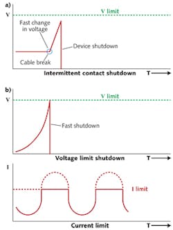
High-speed voltage limits provide critical protection for the laser (see Fig. 1). When the voltage limit is exceeded, the laser driver should power down immediately. In powering down, the laser driver accomplishes two things: first, it protects against excessive voltage; and second, it responds to an open-circuit condition by shutting down the laser before the circuit can be closed, which could allow a massive current spike.
An intermittent contact safeguard is a hardware feature that will power down the laser circuit in the event that a bad cable or connector causes an intermittent electrical contact. While voltage limit protection, as previously described, provides a degree of protection against open-circuit conditions, intermittent contact safeguards measure the rate of voltage change and therefore can trigger a shutdown even more quickly.
Current limit features, in contrast to voltage limits, need not power down the system. Instead, the laser diode driver should treat the current limit as a maximum value that cannot be exceeded—particularly important when using a function generator or power mode control.
Constant optical power mode, or the ability to use photodiode input as a feedback signal, will expand the laser driver's utility for a variety of applications. The photodiode measures the optical power produced by the laser and, in using this measurement, the driver can regulate optical output power over extended periods regardless of the temperature or changes in performance as the laser ages.
Temperature control
Lasers release heat as they operate and are highly sensitive to fluctuations in temperature. Most laser applications require careful temperature control to achieve an acceptable level of performance. For some applications, a passive heat sink will dissipate heat energy sufficiently. However, many applications require active temperature control that is typically provided by a thermoelectric cooler (TEC) module, either inside the laser itself or in the fixture onto which the laser is mounted. For systems using a TEC, a temperature controller is also required to power the TEC module (see Fig. 2).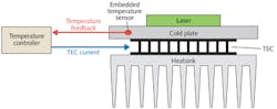
Most users find it preferable to purchase the thermal system components from the manufacturer of the driver they have selected. Within the selection of devices offered by that manufacturer, the power ratings, thermal capacity, and the type of laser in use will help narrow down the correct choice.
In selecting temperature control components, it is important to distinguish between two specific terms: (1) thermal load, measured in watts, describes the amount of heat generated by the laser; (2) thermal capacity, also measured in watts, is the maximum amount of heat the mount can dissipate at a given laser temperature set point and ambient temperature. Thermal capacity should be calculated for the worst-case scenario, which occurs at the highest ambient temperature and lowest laser temperature set point.
Determining the thermal load for a laser system begins with the laser. When a laser is powered, a certain amount of the electrical input energy is converted to light, while the remaining electrical power is converted to heat (see Fig. 3). Start by calculating the electrical input power using the equation P = IV, where P is power (in watts), I is current (in amps), and V is voltage (in volts); for example, if the laser operates at 8 A and 2 V, the electrical power will be 16 W. Thermal load is then simply the supplied electrical power minus the optical output power, as specified by the laser manufacturer. In this case, if the optical power was 7 W, then the thermal load on the temperature-control system will be 16 minus 7 or 9 W.
Thermal capacity must be greater than the thermal load applied to the system. The thermal capacity of commercially available mounts is often specified at an ambient and plate temperature of 25°C, with a de-rating curve for operation outside these parameters. Select a mount with at least 10–20% higher thermal capacity than is needed at your ambient and set temperatures to allow for variations in device performance and fluctuations in ambient temperature.
Wiring considerations
Generally, the wiring configuration will vary with the type of laser and mount. Typical connections include the laser, photodiode, TEC, and temperature sensor. Other connections might include fan power, four-wire voltage sensor for the laser, and four-wire measurement for the temperature sensor. Improper wiring in the mount or in the laser cables is the most common mistake in setting up a laser system.
Purchasing the driver, temperature controller, and mount from the same manufacturer typically minimizes the risk of incorrect wiring, as the instruments, cables, and mounts should be designed to work together. However, due to the variety of laser pin configurations, there is still often a need to configure the mount for the specific laser device.
Limits
Setting the appropriate limits on the laser driver and temperature controller is a critical step. These limits can be found in the datasheet for the laser or temperature-controlled mount.
On the laser driver, set the current and voltage limit. If the manufacturer specifies the maximum operating current, set the current limit to that value. Otherwise, set the current limit to 10% above the normal operating current of the laser. The voltage limit should be 0.5 to 1 V above the normal operating voltage, or the maximum operating voltage, whichever is lower.
On the temperature controller, the TEC current limit should be set to the maximum TEC current rating of the laser or mount. To prevent false temperature-limit errors, the temperature's high and low limits should be set to 5 degrees outside the operating range, as the temperature controller will slightly over- and under-shoot when changing temperatures.
For the first power-on, set the laser driver current to zero. Set the temperature set point to the desired temperature (typically 25°C) and turn on the temperature controller. Wait for the temperature to stabilize at the set point, and then turn on the laser driver. The laser should power-on without triggering any error messages from the laser driver. Slowly ramp the laser set point up to the desired operating point. Once proper operation is verified, there is no need to ramp the current from zero each time. Simply leave it at the set point and turn the laser driver on and off.
If a function generator is a part of the application, make sure to complete the above tests before connecting the function generator. When using a function generator, setting the current limit is critical, as it is very easy to accidentally select a modulation input that is beyond the limits of the laser. Function generators are also common causes of ground loops, as the signal ground is commonly connected to earth ground. Be sure that the addition of a function generator does not cause a ground loop through the system.
Safety and laser workstation setup
Working with lasers is potentially dangerous. A single accidental exposure to direct or reflected laser light, even at low power levels, can cause irreversible vision loss. For example, a 1 mW helium-neon (HeNe) laser shining directly into the eye can produce a power density that is well over 100X that of direct sunlight.
At a minimum, users should be aware of where laser light and its reflections are directed and make sure that no one looks directly into the beam. Laser goggles and protective enclosures such as curtains or portable panels are common methods of eye protection, and laboratories should be equipped with illuminated "laser active" signs, interlocks, door switches, and other safeguards.
Electrostatic discharges (ESD) are a high-voltage source of energy. An ESD strike can deliver an instantaneous charge well over 20,000 V! This level of voltage, however brief, is sufficient to jump the electrical resistance between points on the laser package and permanently damage the laser. Protecting a laser from ESD is critical to ensuring long-term operation.
To avoid damage, your workstation must be ESD-safe before removing the laser system components from their packaging and at all times while working with your laser (see Fig. 4). Technicians should wear ESD wrist straps and the optical table should be grounded. If your workstation includes a rolling chair, that chair should also be grounded (alternatively, you can also ground yourself, each time, before handling the laser) and the laboratory flooring should be tiled, as carpeting may produce static electricity as you walk.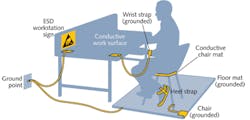
As laser applications continue to take hold across numerous industries, new users armed with the right information, the right instrumentation, and the right setup will be able to optimize their laser tool for the task at hand.
Paul Corr is president and Patrick Klima is marketing manager at Arroyo Instruments, 624 Clarion Court, San Luis Obispo, CA 93401; e-mail: [email protected]; www.arroyoinstruments.com.