QUANTUM-CASCADE LASERS: High-power QCL MOPA array aims for spectroscopy
For use in mid-infrared (mid-IR) spectroscopy, multiwavelength arrays of single-wavelength quantum-cascade lasers (QCLs) can in some cases serve as an alternative to single but tunable QCLs. While the disadvantage is that only certain wavelengths are available, the advantage is purely electronic addressing of different wavelengths.
Federico Capasso’s group at Harvard University (Cambridge, MA), along with Christine Wang of MIT Lincoln Laboratory (Lexington, MA), has compared two of their own designs for multiwavelength QCL arrays. Both rely on master-oscillator power-amplifiers (MOPAs) to boost the power, but each one differs in the details of the MOPAs’ distributed-feedback grating arrangements (dubbed Array 1 and Array 2 for the study).1 The researchers have shown that the more recent Array 2 design is superior.
It should be noted that, along with Capasso and his group, other well-known researchers have contributed to the overall body of knowledge for QCL-array technology—for example, Manijeh Razeghi and her group at Northwestern University (Evanston, IL), and a team that includes Claire Gmachl of Princeton University (Princeton, NJ); Gmachl is also director of the Mid-InfraRed Technologies for Health and the Environment (MIRTHE) Center at Princeton University.
Array comparison
Both Array 1 and Array 2 are composed of gallium indium arsenide/aluminum indium arsenide (GaInAs/AlInAs) lattice-matched on an indium phosphide (InP) substrate. Results for Array 1 were first presented in 2012.2 Array 1 operates at a number of wavelengths between 9.2 and 9.8 μm, with singlemode peak powers between 0.8 and 3.9 W.
As does Array 1, Array 2 has 16 QCL MOPA devices, with each MOPA having two sections—a DFB ridge serving as a master oscillator (MO), and a tapered power amplifier (PA). The geometry of both arrays is identical except for the DFB grating design. While Array 1 relies on quarter-wave-shifted (QWS) DFB sections, Array 2 has conventional first-order Bragg gratings—a simpler approach. The MO and PA portions are each 2 mm long, with an antireflection coating on the output facets of the PAs.
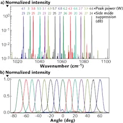
Each element of Array 2 was pulsed at a 10 kHz rate with a 25 ns pulse duration exiting the PA, resulting in a 0.025% duty cycle. The maximum peak output power of each MOPA element was determined, with the requirement that the side-mode suppression ratio (SMSR) be at least 20 dB, as monitored by a Fourier-transform IR spectrometer. The spectrum of the array shows individual wavelengths that range between about 1025 and 1088 wavenumbers, or 9.75 and 9.2 μm (see figure). Two of the elements (1 and 16) were flawed, and thus 14 individual spectra are evident. All peak powers are under singlemode operation, with Device 9 faring the best by reaching 6.8 W.
The researchers note that the highest singlemode peak powers were achieved for elements that simultaneously drive the MO close to “rollover” (the point where increased input electrical power no longer increases output optical power) and of the PA close to its self-lasing threshold.
In comparison to Array 1, with its more complex arrangement, Array 2 showed comparable average threshold currents, slightly higher slope efficiencies, and much higher singlemode peak output powers, with Array 2 reaching between 2.7 and 10 W, and Array 1 reaching between 0.8 and 3.9 W. The researchers attribute the much higher peak powers of Array 2 to its greater stability for singlemode operation.
Device 9 in Array 2 operated especially well, as it was the only element that remained in singlemode operation well above its self-lasing threshold. Analyzing Device 9 in comparison to the other elements, the researchers learned that increasing the taper angle of the PA section could improve operation by shifting gain saturation to higher powers through a longer adiabatic propagation of the mode in the amplifier.
With its higher peak powers, the Array-2-type QCL MOPA array is suitable for standoff detection and other spectroscopic applications, the researchers note.
REFERENCES
1. P. Rauter et al., Opt. Exp., 21, 4, 4518 (2013).
2. P. Rauter et al., Appl. Phys. Lett., 101, 26, 261117 (2012).
About the Author

John Wallace
Senior Technical Editor (1998-2022)
John Wallace was with Laser Focus World for nearly 25 years, retiring in late June 2022. He obtained a bachelor's degree in mechanical engineering and physics at Rutgers University and a master's in optical engineering at the University of Rochester. Before becoming an editor, John worked as an engineer at RCA, Exxon, Eastman Kodak, and GCA Corporation.