OPTICAL FIBER FOR TELECOMMUNICATIONS: Rugged fiber will serve the home network
Even taking into account the wide variety of applications of photonics, it is always exciting when a new application of leading-edge photonics begins to make its way into the home. When this happens, the result can be a transformation for the consumer.
The change can be overt, as in the case of CD, DVD, and Blu-ray laser read/write technology, which banished fragile vinyl records and clunky, wear-prone videocassettes from most people's homes; or it can be more subtle, as when the modern optical mouse, which usually has a vertical-cavity surface-emitting laser (VCSEL) at its core, replaced trackball-type computer mice and the onerous, repeated disassemblies and cleanings required of them.
Now, researchers at Corning Inc. (Corning, NY) and Intel (Santa Clara, CA) are developing new optical fibers whose ultrasmall bend radii make them well suited for short-reach, high-data-rate optical interconnects in the home (while Laser Focus World briefly covered this in a recent newsbreak, the topic warrants a bit more exploration).1
Fiber-optic data links have already found limited use in the home in the form of Sony/Philips digital-interconnect-format (S/PDIF) fibers used by audio enthusiasts to carry a digital audio stream between a CD, DVD, or other device to a digital-to-analog converter for output to loudspeakers. These fibers have a bit rate of up to 125 Mbit/s—overkill when used for audio, but nowhere near the 10 Gbit/s that is fast becoming the next standard for the sophisticated consumer (for example, as found in Intel's Light Peak data-link technology, first introduced recently in Apple's computers as the Thunderbolt interface).
Bend-resistant fibers have also been created for short-haul use, both in data centers and for fiber-to-the-home (FTTH) applications such as wiring up apartment buildings. However, both these applications have backward-compatibility requirements that limit the design of new fibers—and thus the amount of protection from bend-related fracture and optical bend loss that can be designed into a fiber.
Smaller diameter design
To develop the new fiber, the Corning research team initially engaged with Intel as early as 2008, says Kevin Twomey of Corning. "This was a very collaborative effort, and we shared modeling and prototype resources prior to the launch of the Light Peak solution," he notes, adding that the desire was to create a low-cost solution by enabling as much automation as possible in the module assembly process. "The end users that Intel engaged with were also looking for a very robust design that could withstand use in the hands of a consumer population that would not be familiar with handling glass fiber," says Twomey.
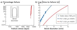
The prototype fiber developed by Corning and Intel is designed to be used with low-cost VCSELs. The fiber has a seven-year lifetime at a 10 mm bend diameter for permanent deployment, and a one hour survival time at an impressively small 3 mm bend diameter, which allows the fiber to withstand cable pinches and other mishandling by unskilled consumers who are routing their own home networks.
To achieve this mechanical flexibility, the fiber has a smaller outer diameter (100 μm) than conventional communications optical fiber (125 μm); this change drastically increased the fiber's flexibility (see Fig. 1). While such a change would seem straightforward, it adds its own complications. "The biggest issue expressed by our customers was the requirement to have to use 100 μm ferrules rather than the traditional 125 μm ferrules; the issue was cost," says Twomey. "To overcome these concerns, we incorporated an additional hard-coat layer to bring the diameter up to 125 μm. This allows customers who prefer to use traditional 125 μm ferrules to strip the protective coatings down to the 125 μm hard coat and operate as before."
There is another set of customers who prefer to laser-strip the fibers down to the 100 μm glass and use 100 μm ferrules, explains Twomey. "It is Corning's belief that 125 μm and 100 μm ferrules will come to the same cost level as the consumer market grows," he says. "Corning's design covers both 100 μm and 125 μm needs."
To reduce optical bend losses, the fiber has a 10-μm-wide low-refractive-index glass "trench" surrounding the fiber's gradient-index (parabolic profile) 80-μm-diameter glass core. The dimensions and refractive indices were arrived at through careful consideration. "It was a combination of experiment, modeling, and previous Corning know-how," says Twomey. "One of the prime drivers behind the development was that the fiber had to be very robust for in-home networking and the consumer markets. All of the work was then validated using experimental fibers. We drew many different fiber types and profiles before settling on the final product. The main tradeoffs were core size (for low-cost alignment with VCSELs), required bandwidth for in-home networking, and bend capability of the fiber for robust cable designs."
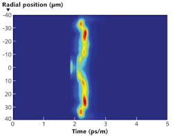
In one example, Corning manufactured a number of different optical fibers with trench profiles and measured the differential mode-delay (DMD) profiles of all of them by scanning the source across the core of the fiber in 0.2 μm steps (see Fig. 2). A particular fiber was chosen for its low DMD, which allows the lateral alignment tolerance of the source to the input fiber end to be as loose as possible.
Links pushing to 100 m
Data-transmission tests were done using an 850 nm, 10 Gbit/s VCSEL and a high-speed photodiode in a setup including other elements such as expanded-beam connectors and "photonic turn elements" (prisms with integrated lenses). However, unlike commercial VCSEL-based transmitters, the experimental setup did not include active electronics to shape the electrical pulses driving the VCSEL; this was done to allow full experimental control of both the VCSEL's modulation amplitude and DC bias. Such a capability was necessary to produce a controlled reduction of the optical power at the receiver; this was done by reducing the modulation amplitude while keeping a constant DC bias to simulate a variable optical attenuator (VOA). (A real VOA was not used because commercial VOAs introduce too much mode-dependent loss and mode coupling.)
Typical results for a 50-m-long fiber with a 682 MHz-km bandwidth showed a power penalty of -0.3 dB. Different fibers with differing DMDs were tested; a fiber with higher DMD and thus a bandwidth of 232 MHz-km showed a penalty of at most 1 dB; a fiber with low DMD and an 800 MHz-km bandwidth had a penalty of 0.1 dB, which was equal to the experimental repeatability of the setup.
"Next steps for the fiber will be improving the bandwidth as end users push the capabilities further," says Twomey. "Our initial efforts were targeted at tens of meters but we are now seeing the 'pro-consumer' community pushing that to up to 100 m. Uncompressed video signals and video-editing applications are some of the key drivers in this pro-consumer space."
The Corning and Intel group is seeing an increase in centralized control in higher-end residences, notes Twomey. "Everything from Blue-ray, TV, music, lights, window shades, climate, power and security being integrated and centrally controlled," he says. "This fiber enables contractors and installers to effectively route cables through tight bends while maintaining the required bandwidth and robustness that in-home networks demand."
REFERENCE
1 .P. Dainese et al., Opt. Expr., 20, 24, 26528 (Nov. 19, 2012).
About the Author

John Wallace
Senior Technical Editor (1998-2022)
John Wallace was with Laser Focus World for nearly 25 years, retiring in late June 2022. He obtained a bachelor's degree in mechanical engineering and physics at Rutgers University and a master's in optical engineering at the University of Rochester. Before becoming an editor, John worked as an engineer at RCA, Exxon, Eastman Kodak, and GCA Corporation.