PHOTONICS APPLIED: METROLOGY: Stitching interferometers: Direct imaging aids asphere metrology
Phase-shifting interferometry (PSI) has been around for decades and has continued to improve through developers' skills and increased computing power. It is now the most common method for optical surface metrology and there are commercially available instruments available with a range of capabilities.
Though PSI has improved interferometric measurement accuracy and ease of use, it has not solved some fundamental geometry problems. Large and/or steep convex spherical surfaces and flats require large-aperture interferometers that are impractical to manufacture and sell commercially. Also, most aspheric surfaces have too much departure from a sphere to be tested alone and generally require null optics, computer-generated holograms (CGHs), or complex geometric null-test setups in order to measure them interferometrically.
In 2004, QED introduced the SSI, the first commercially available stitching interferometer designed to measure large spheres and flats. Aspheric surface metrology capability (SSI-A) was added in 2007, and its capability further expanded in 2009 with the introduction of the aspheric stitching interferometer (ASI) and its variable optical null (VON). These systems all rely on PSI and use a commercially available Fizeau interferometer as part of the system. Although this interferometer has worked well, it was designed primarily for testing under null conditions. It was soon realized that there was a need for an instrument better suited to stitching interferometry.
Direct imaging
Stitching interferometry is performed by collecting interferometric data from overlapping subapertures and stitching these data together to render a full surface map. The data collected for aspheres is inherently non-null. For any given part, the goal is to design a lattice with the minimum number of subapertures to minimize measurement time. As subapertures become fewer and larger, fringe densities become very high, leading to phase unwrapping problems, data dropout, and failure to acquire data.
The typical commercially available interferometer is designed primarily for use at null. The interference pattern is imaged to a moving diffuser disc and re-imaged with a zoom system to a 1000 × 1000 pixel CCD. This zoom system softens the image and reduces modulation at the camera, thereby limiting the ability to reliably acquire fringe densities beyond approximately 70% of Nyquist.
The QED interferometer for stitching (QIS) is a direct imaging system available in the ASI and SSI-A platform. There is no imaging screen or zoom relay; the interference pattern is imaged directly onto a 1200 × 1200 pixel CCD. This allows for reliable acquisition of fringe densities greater than 90% of Nyquist.
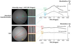
Modulation vs. fringe density was compared for a standard interferometer and QIS (see Fig. 1). The interferogram from the standard interferometer contains 400 tilt fringes; the QIS interferogram contains 530 tilt fringes. As intensity variation affects modulation, the 95th and 5th percentile modulation regions are shown for comparison. It is evident that QIS maintains high modulation independent of fringe density, while modulation in the standard interferometer falls off dramatically with fringe density.
To directly compare the measurement benefits, a 46-μm-departure asphere was measured using both instruments. A lattice design consists of a transmission element and the associated array of subapertures for a given surface under test; the ASI/SSI software recommends lattice design choices based upon the aspheric prescription and the interferometer properties.
Recommended lattice designs and acquisition results are compared for the two interferometers (see Fig. 2). A 6 in., f/5.3 transmission sphere is recommended for the standard interferometer, which yields a lattice with 109 subapertures and a measurement time of 19 min. The subapertures are fully filled and a quality result is obtained. For QIS, a 6 in., f/3.2 transmission sphere is recommended, yielding a lattice with 64 subapertures and a measurement time of 11 min. Again, a quality result is obtained.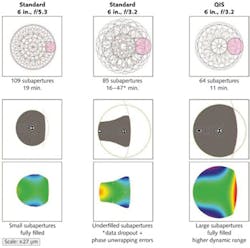
However, when the standard interferometer is used with a 6 in., f/3.2 transmission sphere, the resultant lattice contains 85 subapertures and a predicted measurement time of 16 min. This was not achievable, however, due to high fringe densities and unreliable phase unwrapping; the actual measurement time was 47 min once measurement retries were allowed.
Pixel scale
There is another advantage to eliminating the zoom system. Precise lateral calibration is typically not a concern for general, full-surface metrology. However, knowing the relationship between image and object size is very important for stitching interferometry. This is calibrated in the ASI/SSI, but any variation can cause errors in the metrology.
The minimum zoom setting in the standard interferometer is approximately 1X but is not always consistent from interferometer to interferometer nor is it always repeatable within a given interferometer. Each standard interferometer must be characterized. Changes to zoom settings are possible during use with the standard interferometer and cause errors in the metrology. This problem has been eliminated in QIS with its fixed-magnification, telecentric design.
Retrace error
As an interferometric test setup deviates from null, retrace error becomes more of a concern. At non-null conditions, rays reflecting off the part under test take a different path on the return trip through the instrument, and aberrations in the interferometer can therefore increase measurement uncertainty.
Because this problem is addressed in the QIS optical design, fabrication and retrace errors are reduced in comparison to the standard interferometer. The retrace error was compared for the two systems (see Fig. 3). The ASI/SSI software and calibration procedures deal with alignment errors and low-order aberrations that impact retrace. High-order residual error, however, is a direct contributor to measurement uncertainty. The data show that while low-order retrace is similar, high-order retrace is improved.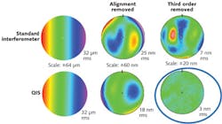
Focus
To perform the most accurate metrology, it is important that the surface under test be in focus. Defocus can limit the ability of the instrument to detect small features and mid-spatial-frequency errors. Wavefront propagation errors also occur in uncompensated, defocused conditions. This becomes more important in non-null test conditions.
The standard interferometer has a reasonable focus range that supports most general testing conditions. However, this range puts limitations on stitching in the ASI/SSI platform. With a standard interferometer, the ASI/SSI system requires the user to manually set paraxial focus prior to measurement. This requires putting an object (for example, a piece of paper) on the surface of the part and manually adjusting focus of the interferometer. The focus is then fixed at the paraxial setting during acquisition of the lattice. This is not an issue for spheres and flats but can become a problem for certain aspheres with local radii that vary significantly from paraxial focus.
Because the QIS focus range is nearly double that of the standard interferometer, it can focus on steep concave or convex radii. With QIS, the ASI/SSI system sets focus automatically based upon the part geometry entered into the software. This eliminates the need for the manual process described (although this option is still available). The system also automatically varies focus for different radial positions on the part under test. This reduces measurement uncertainty for aspheres and improves the ability to measure certain aspheres with local radii that deviate significantly from the paraxial radius.
While the standard interferometer has its own software that must communicate with the ASI/SSI software, the QIS software is integrated into QED's .NET software platform, allowing for improved metrology algorithms, better communication, and a common look and feel.
ACKNOWLEDGMENT
SSI, SSI-A, and ASI are registered trademarks of QED Technologies. VON and QIS are trademarks of QED Technologies.
About the Author

Chris Bond
Optics and Systems Engineering Manager, QED Technologies
Chris Bond joined QED Technologies as Optics and Systems Engineering Manager in July 2011. Prior to joining QED, Chris spent 20+ years in the optics industry working on product development in the capacity of Technical, Program and Business management and as a metrology engineer. Chris received his Bachelor of Science degree in Optics from the University of Rochester.