MICROSCOPY: Programmable LED array makes microscopes more versatile

The use of a programmable LED array enables different imaging approaches for optical microscopy, including darkfield imaging, motionless stereo and 3D imaging, pixel-shifting super-resolution imaging, and high-dynamic-range imaging.
GUOAN ZHENG
Most modern laboratory microscopes are equipped with a Köhler illumination setup, which includes a halogen (or mercury) lamp, a collector/condenser lens, and a field/condenser diaphragm. While the Köhler setup is capable of delivering uniform light intensity over the entire specimen free from glare, it is still considered a passive illumination scheme with limited controllability.
To address this limitation, active lighting systems are being developed that add a new dimension of light controllability for microscopy illumination design. With the maturation of LED technology in the past years, the use of a programmable LED array as the active illumination source enables greater imaging flexibility and functionality in microscopy imaging. Specifically, such a programmable LED array can be used for brightfield, darkfield, stereo imaging, 3D imaging without mechanical scanning, pixel-shifting super-resolution imaging, and high-dynamic-range imaging.
Brightfield, darkfield, 3D, and stereo imaging
The condenser lens of a conventional microscope can be replaced by a programmable LED array for brightfield, darkfield, and 3D imaging (see Fig. 1).1 For brightfield imaging, the illumination numerical aperture (NA) is matched to the collection NA of the objective lens, and thus we can simply turn on the LEDs in the central region of the array, as shown in Fig. 1 (b-1). For darkfield imaging, the illumination NA should be larger than the collection NA of the objective lens, and we can turn on the LEDs at the edge of the array, as shown in Fig. 1 (c-1). The corresponding brightfield and darkfield images of a starfish embryo by using this scheme are also shown in Fig. 1 (b-2 and c-2).
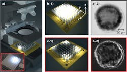
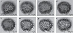
The programmable LED array can also be used for 3D and stereo imaging without mechanical scanning.1,2 Each individual LED illuminates the specimen at a specific incident angle; therefore, each frame of the captured image provides a unique perspective view of the specimen. Conceptually, such a scheme is similar to a computed tomography (CT) scan, where the sample is mechanically rotated to provide different perspective views. Therefore, we can reconstruct the 3D image of the specimen by using the Fourier slice theorem. The reconstructed images of a starfish embryo (at different depths) are shown in Fig. 2.
The aforementioned imaging methodologies can be accomplished simultaneously by a single LED scan process. Because no mechanical moving parts are involved in this scheme, the imaging speed is only limited by the capturing frame rate of the camera.
Pixel-shifting super-resolution imaging
Pixel-shifting technology has been used in a few high-end digital cameras, such as the Leica DC500, Zeiss Axiocam, and Nikon DXM1200. The principle of pixel-shifting camera is shown in Fig. 3 (a-1). Such a camera captures nine images of the same object. In between the single captures, the image sensor is sub-pixel-shifted by a precise mechanical microscanning process. After the image acquisition, an image reconstruction process is performed to render a final image with higher spatial resolution (smaller effective pixel size).
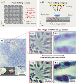
The pixel-shifting imaging technique can also be implemented with a simple programmable LED array.3,4 As shown in Fig. 3 (a-2), the sample—which can be either a real sample or a virtual image—is placed in front of an image sensor. With a tilt illumination from the LED array, the shadow projection of the sample is sub-pixel-shifted across the image sensor. Three shadow projections can be seen corresponding to three individual LEDs in the array (see the color code for matching). The amount of shadow shift is proportional to the thickness of the transparent spacer and the tilt/shift extent of the light source. As long as the shadow shift between each raw image frame is smaller than the physical pixel size, we can then combine the information from multiple sub-pixel-shifted, low-resolution shadow images to create a single high-resolution image with a pixel-shifting reconstruction technique.
Figure 3b shows the reconstructed color image of a confluent HeLa cell sample using the pixel-shifting technique with a programmable LED (HeLa is an immortal cell line used in biomedical research). Figs. 3c-1 and d-1 show the raw images from a small region of Fig. 3a. Figs. 3c-2 and d-2 are the corresponding high-resolution images of 3c-1 and 3d-1 reconstructed by using the pixel-shifting technique. From these reconstructed high-resolution images, we can readily discern organelles within the HeLa cell such as multiple nuclear granules (indicated by red arrows) and the nucleus.
High-dynamic-range imaging
By switching and dimming each LED, the programmable LED array can easily deliver light emission into highly structured patterns for image-like illumination.5, 6 High-dynamic-range (HDR) imaging is one application of this type of illumination scheme. The typical dynamic range of a high-end microscope camera is 55–70 dB. An obvious approach to increase the dynamic range using the programmable LED array (or other microprojection devices with addressable LED pixels) is to project the inverse reflection/transmission map to the sample. In this regard, the combination of a 35 dB projector and a 50 dB camera can deliver an 85 dB HDR imaging system.
REFERENCES
1. G. Zheng et al., Opt. Lett., 36, 3987 (2011).
2. J.S. Dam et al., Opt. Exp., 16, 7244 (2008).
3. G. Zheng et al., Proc. Natl. Acad. Sci., 108, 16889 (2011).
4. W. Bishara et al., Opt. Exp., 18, 11181 (2010).
5. E.C. Samson and C.M. Blanca, New J. Phys., 9, 363 (2007).
6. I. Moreno, Opt. Lett., 37, 839 (2012).
Guoan Zheng is a PhD student in the electrical engineering department of the California Institute of Technology, Pasadena, CA 91125, USA; e-mail: [email protected]. Zheng is the recipient of the Lemeson-MIT Caltech student prize for his contributions to microscopy imaging.