CCDS AND MICROSCOPY: Real-time 3-D microscopy enables viewing of specimen dynamics
Because a standard confocal microscope efficiently images only regions of a specimen that lie close to the focal plane, producing a 3-D depiction requires that the microscope refocus and image a series of closely spaced planes. Summing the component sections to create an extended-depth-of-field (EDF) image is simple enough, but producing sequences of EDF images in quick succession (to monitor dynamic behavior in a specimen, for instance) is not. It takes a while for confocal microscopes to refocus: the only way to do it, without introducing aberration, is to keep the image plane fixed and change the physical distance between the objective lens and specimen mechanically.
Attempts to overcome this limitation–by manipulating the system point-spread function to gather data from a range of specimen depths on a single image–have produced images of compromised quality. But researchers at the University of Oxford (Oxford, England) have developed a novel focusing method that enables high-speed EDF image acquisition directly on a CCD camera without compromising the system transfer function (see Fig. 1).1 They have applied the remote method to real-time Nipkow disc microscopy, and demonstrated how the user can alter the images’ apparent angle of perspective in real time.
“The method is noninvasive and fast,” says Oxford professor Tony Wilson. “No mechanical movement takes place near the specimen, and the focusing mirror can be made extremely small for rapid repositioning. Thus, it is possible to use a resonance technique to permit focusing rates well into the kilohertz region. In our study, the speed of the CCD camera we used was the only limitation for image acquisition.”
With their setup, the researchers were able to acquire EDF images directly in single frames taken by the CCD camera. At any instant in time, the CCD camera records information from a particular region (R) of the specimen that lies in the EFP. Refocusing the system changes the position of the EFP and therefore has the effect of sweeping R through the specimen axially. An EDF image can therefore be captured by simply sweeping R over a range of depths and integrating the response on the CCD. Information from different layers of the specimen is summed directly on the CCD and no further processing is required. This procedure can be repeated numerous times to generate a real-time EDF movie.
How it works
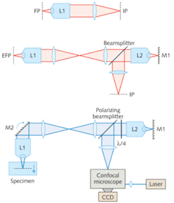
The standard architecture of most commercial microscope systems consists of a high-numerical-aperture (NA) objective lens, and a low-NA tube lens (see Fig. 1, top). A diffraction-limited image of the section lying in the focal plane appears in the image plane where the detector (camera) is placed. If the object shifts axially, trying to refocus by moving the detector along the axis introduces aberration.
The researchers’ design adds a second high-NA objective lens, a mirror, and a beamsplitter (see Fig. 1, center). Here, the image plane is conjugate to an effective focal plane in the specimen; the axial position of the effective focal plane depends on the position of mirror1 in the focal region of lens2. The pupil planes of lens1 and lens2 are mapped onto one another with a 4f imaging system. If the magnification of this 4f system is chosen correctly, then aberrations introduced by lens2 directly cancel those introduced by lens1 when focusing onto different planes.
The researchers combined their fast, remote-focusing architecture with a real-time Nipkow-disc confocal microscope in a system (bottom) that also includes an extra mirror near the pupil plane of lens1. A diode-pumped solid-state laser provides illumination. A polarizing beamsplitter and quarter-wave plate (λ/4) direct illumination light through the system into the specimen and back through to the confocal microscope.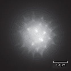
Software controls CCD integration
Custom-created software, written in Labview (National Instruments; Austin, TX), was used to control CCD integration while sweeping M1 through focus. A movie clip of the sweeping view makes it possible to determine without ambiguity which parts of the specimen lie in the foreground and background of the image.
“This approach could also produce a stereo view of the specimen in real time,” Wilson points out. “This can be done by acquiring pairs of EDF images with differing angles of perspective, separated by approximately 12°. A stereo monitor could then display these pairs of images in real time without need for visual aid (for example, red-and-blue glasses) to observe the stereo effect.”
REFERENCE
- E.J. Botcherby et al., Optics Express 16(26) p. 21843 (Dec. 22, 2008).
About the Author

Barbara Gefvert
Editor-in-Chief, BioOptics World (2008-2020)
Barbara G. Gefvert has been a science and technology editor and writer since 1987, and served as editor in chief on multiple publications, including Sensors magazine for nearly a decade.