SOFTWARE & COMPUTING: Ray-tracing model pinpoints cause of stray-light halos
MIKE LARSON
All imaging optics have stray-light issues, which usually appear as ghost images or reflections from non-optical surfaces that degrade the final image. To optimize image quality, camera modules must minimize this unwanted light in the image. During the development of our OptiML wafer-level camera (WLC) technology, we encountered unusual light artifacts such as halos that came from places not intuitively obvious, and that had not appeared in the initial performance simulations. Analysis of these phenomena led to enhancement of the simulation model, due to the discovery that light well outside the apertures and field of view (FOV) was significantly affecting the image.
Conventional camera modules and WLC modules are commonly used in cell phones, with each type of module based on different optical fabrications and assembly methods. Conventional camera modules are built using lenses that are typically individually made injection-molded plastic or molded glass. The lenses are mounted into a barrel and the barrel is mounted onto a sensor; then, the lenses are hand-focused by adjusting the barrel. The barrel assembly is designed with internal stops that can be next to the lens surface or between lenses to block unwanted light.
Wafer-level camera modules are constructed much differently. The lenses are made on wafers using semiconductor-based technologies, which creates thousands of lenses at once on a single glass wafer. The wafer can have a lens on one side or both sides, depending upon design requirements. When multiple lenses are required, the lens wafers are bonded together to create a lens-wafer stack in which the lenses are built in their final position, with no alignment or focus adjustment required. The lens-wafer stack is diced into optical modules that are each picked and bonded to a sensor, producing a camera module that is already in focus. WLC modules have the distinct advantage of requiring no barrels and no manual focusing, but they do require a method to block undesired light. One method is depositing and patterning metal directly on the glass wafer before the lenses are created, resulting in aperture stops.
Characterization of stray light
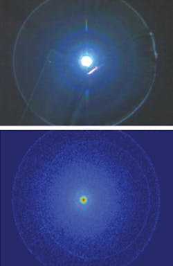
The characterization and evaluation of stray light in the OptiML camera system is an important step in the reduction of stray light. This is done using a black box with an adjustable (for intensity and brightness) LED light source and a 360° rotational stage on which the camera module and demo board sit. The gamma-correction curve in the image signal processing (ISP) is set to a linear curve and the LED is adjusted such that the stray-light images on the camera are not oversaturated. The camera module is then rotated through 90°. The light intensity of each pixel on the camera sensor is captured and the data from the saturated light source is removed. The average intensity per pixel is then calculated to provide an objective value for the amount of stray light in the image (see Fig. 1).
Impact of metal thickness on stray light
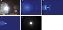
The WLC design uses a patterned chrome metal layer on the wafer to create F-stops and limit the aperture at each lens surface. While evaluating the image, a bright, unexpected halo, which was unaccounted for in the ray-tracing analysis and simulations, occurred in the image (see Fig. 2). The standard models did not predict a halo. To determine the source of the artifact, a set of experiments revealed that the metal aperture was not blocking the light as originally expected. The hypothesis for this gap between standard models and WLC results was that the optical properties of chrome did not match those based on available information. This was verified by allowing the metal layer in the simulation to be a partial transmitter. With this change, the model accurately predicted the images which were taken in the lab. After experimenting with different chrome thicknesses, it was determined that the chrome thickness needed to be doubled for the metal layer to block the light completely. With this change, the halo was completely eliminated.Impact of blend zone on stray light
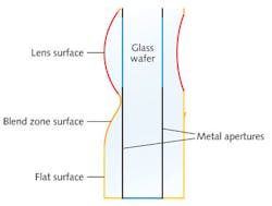
Another difference between a conventional camera system and a WLC system lies in the way the lenses are made. Conventional optics are made one optical element at a time; the area outside the clear aperture generally follows the design curvature and is minimal. Wafer-level optics require a monolithic mold, which can require a blend zone—the transition between the optical design’s clear aperture and the flat region outside the aperture. This is the area between lenses that can be used to bond and/or dice lens wafers (see Fig. 4). The transition area is smooth to eliminate sharp transition zones from lens to wafer, or from lens to lens. Because the blend zone is outside the clear aperture, placing it on top of the chrome layer, it was not initially considered to contribute to stray light.During the work on a multielement, 3 Mpixel WLC module, significant stray-light artifacts were again observed in the image. These artifacts were unaccounted for in the enhanced simulation model. It was determined that the light outside the FOV, which hit the camera at certain discrete angles, caused the large stray-light pattern in the image. These regions of off-axis light were very small and included only 5° to 7° of FOV, but were at angles that made the defect very noticeable in normal usage.
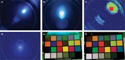
The simulation model was further upgraded to include all blend zones in detail. Only a small portion of the blend zone, located outside the clear aperture, was responsible for the problem. This location was much farther from the aperture than one would typically look in conventional lenses. Many rays were analyzed to identify the offending regions, which revealed that there was a straight-through path involving highly refracted rays through multiple blend zones that was not obvious in the initial analysis. With a more accurate model, the blend zones were redesigned to eliminate all stray light caused by this issue (see Fig. 5).As we discovered through advanced analysis, both the metal-aperture optical properties and the unique characteristics of the regions well outside of the lens aperture caused unforeseen stray-light artifacts. Using a more sophisticated model and applying systematic failure analysis, problems were identified and eliminated to remove stray-light sources and obtain excellent images.
Mike Larson is a senior process engineer at DigitalOptics Corp. (a wholly owned subsidiary of Tessera Technologies Inc.), San Jose, CA; e-mail: [email protected]; www.doc.com.


