POLYMER OPTICS: Progress in plastic optics follows advances in materials and manufacturing
JOHN M. CAVAGNARO
Several recent trends have helped the plastic optics manufacturing industry remain competitive in the United States. In particular, the manufacturing processes for plastic optics have benefited from advances in computer-aided design (CAD), computer-aided machining (CAM), mold flow analysis, metrology software and instrumentation, diamond turning practices, optical process engineering, and improvements in the quality and variety of the raw materials used.
For customers planning to incorporate a plastic optical component into a system design, there are advantages to be gained by understanding the project lead time needs of the plastic optic manufacturer along with the manufacturing process. To meet research and development schedules, single-point diamond turning (SPDT) manufacturing processes are now commonly used in the first stage of a project. This phase of prototyping can be done in parallel with the design and build of a plastic injection mold, bringing initial optical samples to the lab in as soon as four weeks.
Prototyping lenses using SPDT technology enables the use of many optical materials that are also used in production molding. Typical choices include the use of cyclo-olefin polymer (COP), acrylic (PMMA), and polystyrene (PS) grades of resin. While certain grades of polycarbonate (PC) are not desirable for SPDT, comparable resins may be used with similar indices of refraction for development purposes.
When the material choice is polyetherimide (PEI) or polyethersulfone (PES), methods such as High Refraction Diamond Turning (HRDT) developed by Syntec Optics may be used. HRDT is a method for fabricating a lens element using a lens blank shaped from a high index, high thermal property thermoplastic resin such as PEI or PES. The surface is conditioned by a proprietary annealing process that allows SPDT technicians to obtain an optical quality surface. The HRDT method is used with spherical, aspherical, toroidal, cylindrical, cone, and plano shapes, and works with lens surfaces with multiple diffractive structures (see Fig. 1).
Before the HRDT process was developed, polymers for high index, heat-resistant, near-infrared (NIR) optics could only be prototyped using the molding process. Molded prototypes of this nature required from 8–12 weeks lead time. HRDT enables direct diamond turning, lowering costs by two to five times compared to the other molded prototypes.
Surface roughness of 60 Å can be achieved for many geometries, even smoother in some cases using SPDT and HRDT. Capabilities of SPDT and HRDT machining centers allow the use of a C-axis for non-rotationally symmetric applications. If part features create restrictions during assembly testing using these prototypes, there is opportunity for geometry changes before investing in the optical mold tooling design. When bridging the timeline for a molded optical component, SPDT and HRDT are often the best option, bringing the product to market faster.
Understanding the transmission requirements for an optical prototype enables suitable polymers to be selected for SPDT. The types of optics that can be produced using SPDT and plastic optical molding technology include free form, sphere and asphere, parabola and ellipse, toric, diffractive, Fresnel, and mirror.
Material upgrades
In addition to advances in prototyping, progress in material grades has been continuous. Many of these materials must withstand harsh environmental conditions in diverse applications, including the military. For example, when an aircraft drops critical optical intelligence devices from thousands of feet above ground—in the cold air—down to soldiers on hot sandy ground, a drastic temperature shift occurs in a short period of time.
As polymer optics are being used in defense, medical, biometric, and consumer applications, new molding materials are being developed to address related environmental conditions. Grades of PC and others polymers provide shatter-resistant properties, an important factor when using optics near the eye.
Advances in COP materials have resulted in higher heat resistance, enabling greater stability and reducing focal-length change. These developments have decreased birefringence properties found in previous grades.
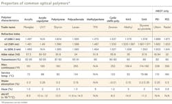
Depending upon the application, other traditional optical polymers such as PMMA, PS, and PC may also be used. The optical properties of all these polymers must be considered in developing applications, including properties related to refractive index, light transmission, Abbe value, specific gravity, melt flow rate, and chemical/environmental resistance (see table).
Manufacturing process
A major consideration when beginning tool design for a plastic optic is to utilize the principle of design for manufacture (DFM) to reduce cost. Precise calculations based upon the estimated annual usage, mold flow analysis, and multicavity options must also be considered when selecting the tooling materials. Proper material selection at the design stage—for both the plastic optic and the tooling—results in a significant reduction in development time and cost.
SPDT can be used to develop and machine optical inserts for the injection mold. Nickel-plated steel is precision machined and SPDT to produce the optical surfaces necessary for the design. Surface roughness of 20 Å can be achieved on such optical inserts. Typical lead times for an optical mold range from 8 to 10 weeks.
Upon completing a new optical mold, a period of testing and refinement of the molding process takes places. This step allows optimization, creating a tighter process window that incorporates a comprehensive mold flow analysis used for the tooling design. The mold processing data are recorded in the control panel of the injection molding press, available on-screen and viewable by the optical molding technician. The captured data are used to monitor and control key process parameters. Design of experiment (DOE) tests are used as a structured environment to test and evaluate process parameters.
When the optical component has passed optical criteria and workmanship standards, a first piece submission is measured by a quality inspector. Additional fine-tuning of the molding process may be necessary. Each feature of the component is measured and documented using precision metrology equipment. Many types of optical surfaces are measured using a combination of a profilometer, standard interferometer, white-light interferometer, and a coordinate measuring machine based on their specific attributes. During the molding process, critical-to-function dimensions are monitored through a series of in-process measurements.
Production parts are qualified through a first-article inspection (FAI) process. Final system testing is qualified based upon the form, fit, and function in their assembly in conjunction with the quantitative data reviewed from the FAI report.
Optical molding process techniques are continually refined and improved when manufacturing challenging components. The repeatability and reproducibility of injection-molded optics for higher volumes is critical and has been shown to meet and exceed military and medical standards and tolerancing. The International Organization for Standardization (ISO) generates criteria for qualifying manufactured optical products. Companies producing plastic optics are generally certified ISO 9001:2008.
The case for plastic optics
The use of plastic in place of glass in an optical lens may have several advantages for the end user. First, unit price is lower when producing high-volume plastic injection-molded optics. Also, a plastic optic weighs considerably less than a glass optic; e.g., the specific gravity of a general grade of COP is 1.01 g/cm3. The specific gravity of a general grade of glass is 2.03 g/cm3, nearly 50% denser than the COP grade.
The amortization of cost savings in addition to the difference in weight has allowed further progress and development of plastic optics in many markets. More sophisticated geometries as well as smaller size requirements have been made possible through plastic optical injection molding.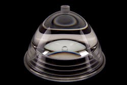
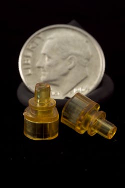
As technology requires smaller and lighter products, assemblies containing plastic optics have been able to meet the size and weight requirements. For example, in a project where a glass optical assembly required a machined aluminum, brass, or steel component for assembly, many of these features are now incorporated into the plastic lens design. It is now possible to add features such as a flange with mounting through-holes on a round optic, thereby reducing the total number of elements in the system (see Fig. 2).
Opportunities for employing laser technology in an assembly have also opened up by using custom plastic optical designs that would otherwise be made difficult if using a glass substrate.
John Cavagnaro is a program manager at Syntec Optics, 7100 Junction Rd., Pavilion, NY 14525; e-mail: [email protected]; www.syntecoptics.com.