PHOTONICS APPLIED: PHOTOVOLTAICS: Not all solar simulators are created equal
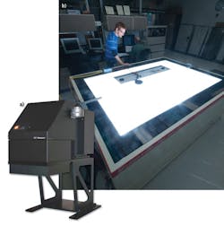
A solar simulator makes possible the accurate measurement of the optical-to-electrical conversion efficiency of solar photovoltaic (PV) cells. The instrument quantitatively simulates the irradiance and spectral output of our own Sun so that PV manufacturers can obtain efficiency data without leaving panels to bake in unpredictable outdoor environments (see Fig. 1). Solar simulators, many with xenon light sources, are available from numerous companies and are distinguished by such factors as whether they are Class A, B, or C; steady state or pulsed; and how well they match the solar spectrum and maintain illumination uniformity over time. Companies that routinely test solar cells and modules should examine the specifications for the various commercial solar simulator options carefully in order to optimize cost and performance tradeoffs.
Standards
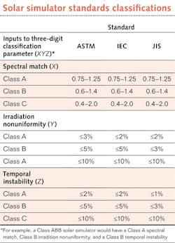
For performance criteria of solar cells and modules (such as conversion efficiency, quantum efficiency, and current-voltage characteristics) to be quantitatively consistent across hundreds of manufacturers, standards for solar simulators have been developed. The primary standards organization that details solar simulator performance requirements, specifications, and test protocols is the International Electrotechnical Commission (IEC; www.iec.ch), although there are several domestic standards bodies such as the American Society for Testing and Materials (ASTM; www.astm.org) and the Japanese Standards Association (JSA; www.jsa.or.jp). The specific standards—IEC 60904-9 ed2.0, ASTM E927-10, and JIS C 8912—classify solar simulators with a three-digit “Class XYZ” designation, where X defines the spectral match (the ratio of the actual percentage of total irradiance to the required percentage specified for each wavelength range), Y defines the irradiance spatial nonuniformity, and Z defines the irradiance temporal instability for the solar simulator (see table). That is, a Class ABB solar simulator meets Class A spectral match, Class B spatial nonuniformity, and Class B temporal instability specifications.
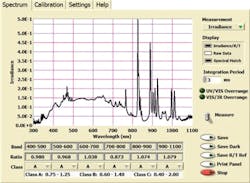
For spectral matching, each standard specifies the percentage of total irradiance from the solar simulator that must fall within each 100 nm wavelength interval between 300 and 1100 nm in order to best mimic the spectral output of the Sun (see Fig. 2). This wavelength range was historically selected to cover the typical absorption region for silicon considering that most early PV cells were single-crystal silicon; however, it does not address the performance of concentrating photovoltaic (CPV) systems that use III-V semiconductor materials with absorption out to 1800 nm and some exotic thin-film PV products.“Even though the ASTM and IEC require solar-cell and module manufacturers to test using a minimum Class BBB and Class ABC solar simulator, respectively, manufacturers would be wise to select a Class AAA solar simulator—or in some cases, even something better—to best optimize their solar-cell manufacturing process,” says Keith Emery, manager of the cell and module performance team at the National Renewable Energy Laboratory (NREL; Golden, CO). As a 31 year veteran within the group that performs “NREL-certified” testing for solar companies worldwide, Emery explains that even a 1% error between the simulator result and actual PV module output is a huge problem for PV manufacturers. “Because cells and modules are typically binned—and priced—according to simulator data, energy efficiency errors translate directly to the bottom line for these companies,” says Emery. “And the aerospace industry goes to even greater lengths to get better than Class AAA simulators; as you can imagine, solar cells that go out into space beyond atmospheric and environmental effects must be engineered to be as small and lightweight as possible. You don’t want to oversize or undersize a module in space.”
Design considerations
Not all solar simulators are created equal. The class differences in solar simulators are largely due to differences in the system optics and the simulator light source.
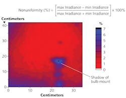
Emery says that while spectral match parameters are relatively easy to correct for, and that temporal stability issues can be overcome by using a reference module during the cell/module qualification process, errors caused by spatial nonuniformity of a solar simulator cannot be numerically corrected (see Fig. 3). “Unfortunately, spatial nonuniformity is caused not only by inadequate homogenization of the beam as it traverses the simulator’s optical path, but it’s also impacted by bulb aging and lamp voltage fluctuations,” says Emery. He also cautions that the near field of a bulb can create short-order peaks that result in different uniformity maps depending on the pixel size over which uniformity is measured, making a Class-A-spatial-uniformity solar simulator something less if the pixel parameters are varied. Emery adds, “These nonuniformities can be particularly problematic if testing smaller solar cells in varying locations across the simulator area.”While continuous source testing can identify hot spots in solar cells (zones that heat disproportionately across the cell or module), pulsed-source simulators minimize cell/module heating; however, many thin-film PV technologies cannot be characterized using pulsed sources as their electrochemical response time—which can be on the order of 50–2000 ms—is longer than the length of the pulse, which is typically 1–100 ms. An exception to this rule is the 3500SLP and 4600SLP Spi-Sun solar simulators from Spire Solar (Bedford, MA), which combine the lower thermal stress of shorter pulse simulators with Class AAA performance. These systems offer an adjustable pulse duration of 20–100+ ms for measurement of both crystalline silicon and thin-film modules with triple (current-voltage) I-V curve generation in a single flash.
Newport Oriel Instruments (Stratford, CT) Class AAA Sol3A solar simulators use several different xenon arc lamps. Depending on the number of starts and end-of-life criteria, a 1.6 kW lamp with a 300 × 300 mm illumination area has a lifetime of about 2000 hours. Newport Oriel simulators are available with a partial sun attenuator accessory that allows users to vary the illumination without shutting down the unit to install neutral density filters or mesh attenuators, avoiding long periods of cooling and restart. This feature makes the Sol3A ideal for linearity studies of efficiency on all types of PV cells using Oriel’s PVIV 2.0 I-V test software, fixtures, and probing capability.
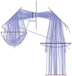
Recognizing that lamp life is an important factor in overall solar simulator system cost, Abet Technologies (Milford, CT) optimized the light path for its Sun 2000 and Sun 3000 steady-state illumination simulators such that only a 550 W rather than a typical 1 kW xenon arc lamp is needed to achieve Class AAA performance for a 156 × 156 mm cell-test area (see Fig. 4). For smaller PV cells, Abet offers a Class ABB simulator with a 25 mm cell-test area under $5000. In 2008, Abet formed a partnership with metrology expert Erik Haverkamp of Radboud University (Nijmegen, the Netherlands) and solar measurement company ReRa (Wijchen, the Netherlands) that allowed Abet to introduce complete I-V test systems that include test stages, electronic loads, and user-friendly and standards-compliant software, as well as solar reference cells.Photo Emission Tech (PET; Camarillo, CA) also manufactures Class AAA steady-state illumination solar simulators with up to 30 × 30 cm cell-test areas, along with I-V test systems.2 “Having worked closely with Yamashito Denso [Tokyo, Japan], who has been manufacturing solar simulators for 30 years, PET solar simulators have several advantages over our competition,” says Mantosh Chawla, president and co-founder of PET. “Rather than a folding-mirror design with one or two mirrors that each suffers an approximate 10% intensity loss, our in-line systems bring light directly to the test surface, using fewer components and enabling a more compact design with a longer lamp life.” Chawla notes that PET can connect to any of its computer-based simulator systems worldwide via the Internet for online troubleshooting.
In addition to continuous-light simulators, Sciencetech (London, ON, Canada) provides Class AAA pulsed and collimated solar simulators for CPV testing. Its fully reflective systems have five choices of xenon lamps between 150 W and 2.5 kW for illuminated target diameters up to 20.3 cm. Fresnel lens systems can achieve collimation to within 0.7º for cell-test areas up to 8.4 sq. in. Sciencetech also has a triple optical path solar (TOPS) simulator that illuminates targets with 30 cm diameters, as well as flash systems to illuminate up to 2 m2 areas. “Many of our noncollimated solar simulators can be purchased with an optional variable focus assembly that lets users tune the power density and target area,” says Jamie Brar, sales and technical support specialist at Sciencetech. “Our fully reflective systems, based solely on mirrors, produce high intensity and uniform illumination by superimposing six images from the lamp source—an advantage over systems using diffusers that reduce intensity, and lens-based systems that introduce chromatic aberration.”
An LED-based simulator?
Researchers at the Bavarian Center of Applied Energy Research (ZAE Bayern) and the University of Erlangen-Nuremberg (both in Erlangen, Germany) are exploring an LED-based solar simulator with improved spectral matching capabilities.3 Unfortunately, while most lamp-based simulators achieve Class A spectral match, deviation from the solar spectrum is still significant—especially in the 800–1000 nm window where crystalline silicon has its peak spectral response. The prototype LED simulator uses 700 specially designed ultrabright LEDs in 22 different wavelengths from 400–1100 nm. Preliminary results show that it successfully simulates the Am1.5 spectrum with a Class A spectral match, can be operated in both steady state or pulsed mode, and offers lower power consumption and longer lifetime than its lamp-based counterparts. Look out, legacy simulator manufacturers: The era of LED-based solar simulators may be on the horizon.
REFERENCES
1. K. Emery, “ASTM Photovoltaic Performance Standards,” ASTM Standardization News, 30–33 (July 2007).
2. M.K. Chawla, “A step by step guide to selecting the ‘right’ Solar Simulator for your solar cell testing application,” Photo Emission Tech application note (2011); www.photoemission.com/techpapers.
3. T. Swonke and U. Hoyer, “Concept for a Real Am1.5 Simulator Based on LED-Technology and Survey on Different Types of Solar Simulator,” Proc. 24th EU PVSEC, Hamburg, Germany, session 4AV.3.24, 3377–3379 (Sept. 21–25, 2009).
About the Author

Gail Overton
Senior Editor (2004-2020)
Gail has more than 30 years of engineering, marketing, product management, and editorial experience in the photonics and optical communications industry. Before joining the staff at Laser Focus World in 2004, she held many product management and product marketing roles in the fiber-optics industry, most notably at Hughes (El Segundo, CA), GTE Labs (Waltham, MA), Corning (Corning, NY), Photon Kinetics (Beaverton, OR), and Newport Corporation (Irvine, CA). During her marketing career, Gail published articles in WDM Solutions and Sensors magazine and traveled internationally to conduct product and sales training. Gail received her BS degree in physics, with an emphasis in optics, from San Diego State University in San Diego, CA in May 1986.
