PHOTOVOLTAICS: Enhancements enable solar simulators to shed light on new photovoltaic designs

JAY JEONG
Although solar simulators are used to test many products, from sunscreen to UV degradation in plastics, their most important role is the testing and certification of photovoltaic (PV) cell and module designs, either as part of validating a new design, or as a quality-control system on existing PV production lines.
The need for advanced solar-simulator testing stations for product development and quality testing is growing right along with the PV market, which is expected to generate annual revenues upward of $23.1 billion by 2010, with the number of installations growing by about 30% each year. Greater awareness of alterative energy sources is fueling PV-market growth and helped to generate more than $1.8 billion in PV-market capitalization in 2005.
Solar simulators help engineers and scientists by providing the tools and data they need to test and optimize new cell designs. The solar simulator is an integral part of the current-voltage (I-V) characterization because I-V measurement requires a calibrated source of insolation (solar radiation power incident on a surface) to illuminate a solar cell. Quantum efficiency (QE) and incident-photon-to-charge-carrier (or current) conversion-efficiency (IPCE) measurements do not require a calibrated solar simulator, only so-called white-light bias. However, the measurements do require careful attention to the spectroscopic measurement techniques.
PV cells and standards
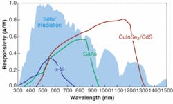
Photovoltaic cells come in two types: higher-efficiency crystalline silicon solar cells (either monocrystalline or multicrystalline), and lower-cost thin-film solar cells, usually composed of amorphous silicon, polycrystalline silicon, cadmium telluride, or copper indium gallium diselenide (see Fig. 1). Recently, thin-film solar cells made of cheap polymer have also attracted considerable attention-these devices are typically constructed monolithically, with a photosensitive layer followed by an electron-transport layer and electrodes to capture the subsequent electron flow.
Although they only make up approximately 7% of the market, thin-film PV-cell installations are growing fast and the amount of research on thin film is growing exponentially. Thin-film cells typically require a continuous-wave (CW) light source because PV Class A certification standards demand time-sensitive measurements, and pulsed insolation can lead to capacitance effects with slow material response times that complicate PV testing.
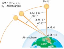
Regardless of design and active material, PV cells are all subject to the same standard test conditions. The cells are typically insolated at a constant density of roughly 1000 W/m2, which is defined as the standard “1 Sun” value, with spectrum consistent to an air-mass (AM) global value of 1.5 (AM 1.5G), at an ambient temperature of 25°C (see Fig. 2).
In addition to these standard test conditions, international standards such as IEC 904-9, JIS C 8912-1989, and ASTM E927-05 define three classes of solar simulation performance-classes A, B, and C. The highest certification level is Class A, whose requirements do not vary significantly among the three international standards (see table).
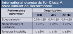
Newport has developed all its Oriel solar simulators to Class A and/or B levels, with products varying by governing international standard, output-beam size, lamp type, power, and collimation. As illustrated by the table, Class A requirements focus on three elements: spectral match, spatial uniformity, and temporal stability.
Spectral match is important because it ensures that test conditions match real-world conditions and eliminate variability from batch-to-batch testing. Spatial uniformity-the most difficult specification to achieve-minimizes “hot spots” that can skew cell performance testing and repeatability. Temporal stability dictates that lamp fluctuations do not distort measurement of solar-cell efficiency.
Simulating sunlight
Newport’s Oriel Class A solar simulator includes several design elements to achieve the highest performance levels for each of these three requirements (see Fig. 3). The simulators start with a xenon arc lamp with various output powers, with the illumination area ranging from 2 × 2 in. to 8 × 8 in. Although researchers typically want to test their designs under “1 Sun” conditions, it is not uncommon to set the illumination at different levels to address a variety of desired test conditions. For example, a 300 W, 2 × 2 in. solar simulator can provide output densities of up to 2800 W/m2, or nearly three times the typical solar irradiance level at sea level with an AM equivalent of 1.0. The simulators also include a control that allows the output levels to be increased or decreased while maintaining the proper spectral ratios necessary to simulate solar irradiance.
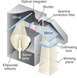
An ellipsoidal reflector collects the lamp output, and a collection mirror directs the light through a single-blade shutter to an optical integrator that ensures uniformity variations of less than 2% across the simulator’s output beam. Beam uniformity is heavily dependent on two design considerations: proper alignment of the optical elements and the optical integrator. The integrator is a monolithic optic that effectively homogenizes the collimated light to within uniformity values listed in international photovoltaic testing standards.
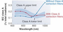
The light then passes through the AM spectral-correction filter, which guarantees that the spectral output varies from international standards by between 0.7% and 1.25%. Newport offers several AM filters, including AM 0, 1, 1.5, and 2. (see Fig. 4).
null
Measuring I-V, QE/IPCE
Repeatable I-V measurements-such as short-circuit current (Isc), current density (Jsc), open-circuit voltage (Voc), fill factor (ff), maximum output power (Pmax) and current (Imax), voltage (Vmax), and cell efficiency (n)-require a reference-cell comparison to calculate the spectral-mismatch factors for different cells and test equipment configurations. The U.S. National Renewable Energy Laboratory (NREL) has improved the situation by offering reference-cell verification.
The Newport Reference Cell is a part of a recently introduced I-V test station that works with either a 2 × 2 in. or 4 × 4 in. beam-output solar simulators. The reference cell is connected to readout electronics that display measured solar simulator irradiance and cell temperature. These values are entered as parameters in the I-V measurement software and are used to generate accurate, repeatable I-V performance.
Proper integration between software, solar simulator, and reference cell is necessary to achieve accurate, repeatable data to calculate the PV-cell efficiency. Once the solar simulator and other instruments are turned on and the cell is placed beneath the simulator, the software will open the solar-simulator shutter, sweep the voltage across the prescribed range, measure the current, and display the I-V curve. Then the software calculates those parameters discussed previously, including the cell efficiency.
Quantum efficiency and IPCE indicates the ratio of the number of photons incident on a solar cell to the number of generated charge carriers. Quantum efficiency is a measure to give an external efficiency, while IPCE considers the internal efficiency; that is, the photons reflected back from the surface of the cell are not considered. The measurement of the optical power versus the output power generated by the cell is called the spectral response. Typically, the result-QE, IPCE, or the spectral response-is recorded as a function of wavelength.
The QE/IPCE measurements are critical-especially during materials research and cell design-because it is of great importance for a device to have an optimal spectral response at the point at which the spectral component of the sunlight is abundant. For example, if the spectral response of a cell occurs in the far-IR, where the intensity from the Sun is low, it is impossible to have a high efficiency.
Despite the existence of standards for PV testing and solar simulation, the industry and research communities struggle under a need to provide accurate and repeatable measurements in the recent burst of photovoltaic-cell research activities. One of the major problems of solar-cell measurement, says Prof. Yang Yang at the University of California (UCLA; Los Angeles, CA), is that different materials have different absorption spectra. One must account for this factor, often called the mismatch factor, in the measurements. Jointly with National Renewable Energy Laboratory (NREL), Prof. Yang’s team at UCLA has initiated a set of standard measurements for plastic solar cells that ensures the accuracy of plastic-solar-cell measurements.
Continuous advancement of solar-simulator manufacturing as well as spectroscopic and electronic measurement technologies may finally give renewable-energy sources such as solar power the edge in the search for new, environmentally friendly energy sources.
JAY JEONG is a product manager at Newport, 1791 Deere Ave., Irvine, CA 92606; e-mail: [email protected]; www.newport.com.