Progress in optical-coating design depends on progress in manufacture

Software tools for the design of optical coatings have become indispensable items in the kit of a coating designer. Nowadays these go well beyond straightforward calculation and optimization of optical performance; they include tools for production planning and even for simulating the manufacturing process.
Developments in optical coating design techniques have always been largely in response to the needs and capabilities of coating manufacture. It is an essentially practical field in which there has never seemed much point in designing coatings that no one could actually produce. Important barriers to progress have been the precision of measurement of material parameters and the stability of the deposition processes and materials themselves, once deposited.
Of course, the first essential in any design tool is a good, reliable model of performance. In the late 1940s, Florin Abelès, in his doctoral thesis, published the matrix method for the design and calculation of optical thin-film coatings that we still use today. It has been proven over and over again in its 60 years of use. Today, commercial coating-design software is to a coating designer as a commercial word processor is to an author. The new design tools are much easier to use, but the underlying basic theory remains the same. Ease of use, rapid delivery of accurate results, and the constantly evolving needs of the industry lead to ever increasing demands for new and improved tools. Optical-coating design software is far from a static product.
The bursting of the dot-com bubble in 2000 was a tragic disaster for many, but for the optical coating field it was a financial, not a technical, disaster. The severe requirements that had been placed on the needed thin-film components had forced rapid and significant advances in almost all aspects of the industry. Energetic processes—ion-assisted deposition and sputtering—had transformed coating manufacture. Moisture-induced instability was no longer a problem. Coatings of several hundred layers of unprecedented accuracy and stability were being manufactured in quantity. The painful contraction of the telecom market resulted in the diffusion of the new technology into the wider optical-coating community with a step-function increase in the confidence of the participants, and new demands on design software.
Run sheets
An optical coating is usually expected to enhance environmental resistance as well as ensure the correct optical properties. Its nature, therefore, is that it is difficult to remove. Frequently, its deposition is the final operation to be carried out on an optical component and a failure at that stage has multiple serious consequences. There has always been a keen interest in ensuring the success of the manufacturing process. Process accuracy and the necessary design tolerances are key factors. The energetic processes have enormously improved the repeatability of the optical constants of the materials, but achieving the correct layer thicknesses still depends directly on all aspects of the control system. Multiple test runs are expensive. Here, modern design software is helping.
A coating design consists of a series of layers each defined by a material and a thickness. In the manufacturing process, the thickness cannot be measured directly but is deduced from the output of a sensor that can range from a simple clock to a complex optical system or an accurate microbalance. In all cases, the relationship between the sensor output and the layer thickness is crucial. Coating design software can naturally be extended to the creation of a "run sheet"—that is, a series of instructions to the controller in terms of the expected signals at layer termination. The run sheet, if followed exactly, will yield a correct coating. However, the question remains: How accurately must the run sheet be followed for an acceptable yield (or, in other words, what are the necessary tolerances)?
Monte Carlo models
The study of tolerances in optical coatings has a long history. It began with analytical models, but what was not realized at the time was just how large actual errors in layer thickness could be. To be tractable, the analytical models were normally limited to first-order effects, implying quite small errors—rather smaller than normal. Later came Monte Carlo models that could incorporate more realistic errors.
The first Monte Carlo models were quite simple, drawing layer-thickness errors from infinite populations of prescribed statistical properties and ignoring any dependence of the error in one layer on that in another. They represented a big step forward, but their predictions for some specialized coatings, such as narrowband filters, suggested that they were impossible to manufacture, when in fact such coatings were being produced. This led to more realistic Monte Carlo models that included details of the monitoring system and error interactions. Not only were errors found to be interacting but under certain circumstances they were compensating each other. Coating design and control techniques were clearly seen to be closely linked.
A more recent thrust in design software has been to model all the important details of the complete process with the aims of reducing the number of test runs and improving production yield. This technique is sometimes referred to as "computational manufacturing." A typical modern coating-design software package includes, in addition to the design tools, a run-sheet generator and a process simulator (see Fig. 1). Before the design is finalized, the run sheet has been tested on the simulation facility, and perhaps, along with the design, modified to ensure the desired yield of acceptable product (see Fig. 2).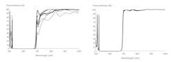
What of the future? Optical coatings serve the entire field of optics and so there will be a constant stream of new needs from the thin-film design community that will require new tools and facilities. Add to this the consideration that optical coatings have properties other than simply optical. Their optical characteristics shift with temperature. They contain strain energy that can reach enormous tensile or compressive levels. They are expected to afford a resistance to environmental disturbances, especially abrasion, heat, and humidity. Optical performance is straightforward because of the excellent existing model. We now have a good model of reversible thermally induced shifts that reveals the key role of the substrate. We have some reversible thermal models of stress, but we know that stress can exhibit significant hysteresis and it depends also on time. Abrasion resistance is at present beyond us. All we can do is use materials known to be reasonably resistant.
About the Author

Dr. Angus Macleod
President and CEO, Thin Film Center
Angus Macleod is President of Thin Film Center Inc, Tucson and Professor Emeritus of Optical Sciences, University of Arizona. He was born in Scotland and after graduating from the University of Glasgow he worked in research, development, engineering, production and management for several UK companies. He was Reader in Thin-Film Physics at Newcastle-upon-Tyne Polytechnic (now University of Northumbria) from 1971 and professor of Optical Sciences at the University of Arizona from 1979. In 1995 he retired from the University to devote his full attention to Thin Film Center. His technical interests are primarily in optical coatings, their design, analysis and production. He has over 200 publications in the area of optical coatings but is probably best known for his book “Thin-Film Optical Filters,” now in its fourth edition.