MID-IR OPTICS: Common-aperture IR imaging systems handle multispectral demands
Traditionally, infrared (IR) imaging systems often had to rely on multiple optical channels, each with a separate optical path, to cover the electromagnetic spectrum because of limitations on available material types and coating capabilities. More recently, systems consolidating two or more channels into a single channel, with a single optical path, have been developed. These use new optical ceramic materials with high optical transmission from visible to mid-IR. Materials with high transmission over a broad range of wavelengths are now commercially available; premier optical-component manufacturers can make these materials into aspheres, spheres, prisms, and domes for use in multispectral systems.
Advantages of the common-aperture system
When dual-channel systems are redesigned for a common-aperture layout, at least one lens in the system receives all wavelengths. The Sniper targeting pod made by Lockheed Martin (Bethesda, MD), for instance, incorporates a mid-wave forward-looking IR (FLIR) imager, a dual-mode laser designator and tracker, and a CCD-TV. The device covers the visible to the mid-IR. Unlike previous systems, Sniper features a common aperture to eliminate boresight errors and ensure image stability even at supersonic speeds. It uses one item in place of two or three, eliminating the need to support the additional systems.1 As a result, Sniper is a more compact and lighter-weight system with a probable lower cost due to fewer components, fewer items to inventory, and fewer part numbers to manage.
Material considerations
In addition to broadband optical crystals such as calcium fluoride, magnesium fluoride, barium fluoride, sapphire, zinc sulfide, and zinc selenide, new optical ceramic materials provide options for engineers designing IR optical systems. Spinel, aluminum oxynitride (AlON), and ceramic YAG are all now commercially available. These materials are heat-resistant, nonmetallic, inorganic solids that are corrosion-resistant and exhibit high hardness. Optical ceramics expand less than optical glasses when heated, which helps prevent system misfocus induced by extreme changes in temperature.2
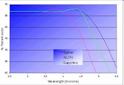
Only a few materials meet the transmission requirements of common-aperture designs. To be a candidate, a material must transmit from the visible to the mid-IR. Choice materials include the ceramics AlON and spinel and the crystal sapphire (see Fig. 1). The transmission of each of these materials tapers off around 5 μm, with slight variations. Their high transmission in the visible through the mid-IR range makes them ideal for common-aperture systems.
Durability is an important attribute to consider when selecting a material. Hard ceramics are able to resist harsh environments, which makes them ideal for specific applications. The thermomechanical properties of optical ceramics make them mechanically strong so they can withstand quick, repeated, and extreme temperature changes. Optical domes, for example, may be exposed to thermal shock, rain, sand erosion, high speeds, and violent aircraft landings. It is critical that the optical materials used to manufacture such domes can endure the elements without breaking or negatively affecting the operation of the system.
Sapphire, polycrystalline alumina (PCA), AlON, and spinel are candidate materials for imaging-system domes. Sapphire has properties critical for defense applications, such as durability and high transmission in the IR, but it is difficult to machine and prone to birefringence. Currently under development, PCA has the potential to exceed the capabilities of sapphire in numerous applications, as it is an isotropic material with mechanical properties that match sapphire.3 Spinel and AlON are more expensive but can withstand extreme weather while requiring only half the weight and thickness of conventional glass substrates.4
Deciding on a material type as early as possible prior to manufacturing increases the likelihood of having enough time to order and receive material and yield finished optics without defaulting on project requirements. The lead time for optical ceramic materials generally stretches across eight weeks once tooling is in place for molding to near net shape. When there is an opportunity to order material for optics that are not strongly curved, slab material is the safer choice because it enables quicker delivery and avoids the risk of molding.
Fine finishing and shaping
Hard ceramic material can be ground and polished to precision tolerances similar to those in optical-glass manufacturing. Researchers at Exotic Electro-Optics (EEO; Murrieta, CA) recorded the process of manufacturing a spinel lens using conventional grinding and polishing techniques. They collected data for visual inspections, surface roughness, grain size, transmittance, strength, index of refraction, and coating characteristics. The results showed that spinel can be polished to typical optical specifications.5
Processes for these materials are evolving and improving, further reducing cost. UltraForm Finishing (UFF), a technique developed by OptiPro (Ontario, NY), is capable of polishing almost any material, from BK7 glass to AlON and transparent PCA, by adapting the slurry to the material. A PCA optic ground to a surface root-mean-square (RMS) figure of 150 nm on an OptiPro eSX150 optical-machining platform can be polished to a decreased surface roughness of 18 nm using UFF. Different polishing parameters will result in reduced surface roughness for AlON as well.6
Optimax has patented a process called VIBE that substantially reduces the time required to process optical ceramics. The high-frequency, random VIBE motion increases removal rates by 10 to 30 times over conventional polishing, which is attractive for processing of hard ceramics. It also has the ability to remove mid-spatial frequencies while maintaining the desired corrected surface form.7 Accordingly, this process can remove subsurface damage as a pre-polish step and eliminate mid-spatial frequency errors as a finishing step.
Relative to traditional diamond-turned IR optics, these processes produce surfaces with lower surface roughness and minimal light scatter, yielding a better signal-to-noise ratio in the IR imaging system. This is of particular importance for optical systems using newer high-resolution detectors.
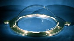
Discussions on manufacturing must include consideration of metrology, especially for strongly curved surfaces like those on an optical dome. Thin, concentric, spherical domes, once manufactured from optical glass or fused silica, are now routinely made from ceramic and crystalline materials. To foster the development of metrology for domes, a test artifact called the OptiDome has been manufactured by Optimax for companies developing optical-dome metrology for use when characterizing the performance of their instruments (see Fig. 2).Coating considerations
Coatings for multichannel optics must accommodate two or more discrete spectral regions, potentially across a strongly curved surface. With advances in thin-film coating technology, coatings are now available to support these requirements. These coatings enable the use of visual systems, keys, laser lines, and night vision in a single optical channel. The optical coatings can be modified for specific wavelengths, angles, and polarizations to meet project requirements.
REFERENCES
1. J. Allen, "Lockheed Martin's Sniper Advanced Targeting Pod Successfully Demonstrates Maverick Missile Compatibility" (2006).
2. E.R. Dowski, Jr. et al., "Wavefront Coding: jointly optimized optical and digital imaging systems," Proc. SPIE, 4041 (2000).
3. M.V. Parish and M.R. Pascucci, "Polycrystalline Alumina for Aerodynamic IR Domes and Windows," Window and Dome Technol. and Mat. XI, 7302, 730205-1-730205-8, SPIE (2009).
4. L.M. Goldman et al., "Large Area ALON Windows for Reconnaissance and Armor Applications," Window and Dome Technol. and Mat. XI, 7302, 730206-1, SPIE (2009).
5. J.R. Bashe and D.L. Hibbard, "Observations during the fabrication of Spinel optics," Window and Dome Technol. and Mat. XI, 7302, 73020C-1, SPIE (2009).
6. S. Banbrick et al., "Recent Developments in Finishing of Deep Concave, Aspheric, and Plano Surfaces Utilizing the UltraForm 5-axes Computer Controlled System," Window and Dome Technol. and Mat. XI, 7302, 73020U-1, SPIE (2009).
7. J. Degroote Nelson et al., "VIBE finishing to remove mid-spatial frequency ripple," http://www.optimaxsi.com/Capabilities/Innovation.php (2010).
About the Author

Brandon Light
Corporate Engineer
Education: BS Chemical Engineering, Louisiana State University
Mr. Light’s introduction to the optics community began with summer employment at Glass Fab in Rochester, New York. This experience led to a position with the University of Rochester’s Center for Optics Manufacturing, followed by his present position at Optimax Systems in Ontario, New York.
Upon his start at Optimax, Mr. Light worked on developing asphere manufacturing capabilities. Through his part in a team effort, Optimax was able to extend its rapid prototype capability to aspheric optics. Currently, Mr. Light supports day-to-day operations of the Optimax Manufacturing Engineering Department.

