ASHLEY LYONS and DANIELE FACCIO
Two-photon interference is a key tool in virtually all quantum optics labs. The specific case where two photons meet at a beamsplitter from opposite input ports and bunch together is named after the principal discoverers, Chung Ki Hong, Zhe Yu Ou, and Leonard Mandel.1 When the two photons are completely indistinguishable, they will bunch together with 100% probability such that they always leave the beamsplitter in the same direction.
Dating back to the late 1980s, the Hong-Ou-Mandel effect was also separately discovered at the same time by Yanhua Shih and Carroll Alley, although with a slightly different experiment, and is now routinely used in quantum computing schemes and to generate what are called two-photon N00N states—a class of quantum state with applications in high-precision interferometry.2
The Hong-Ou-Mandel effect
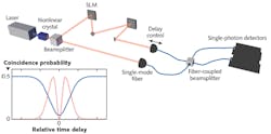
A simple Hong-Ou-Mandel (HOM) interferometer is typically formed of a source of photon pairs, usually based on spontaneous parametric down-conversion (SPDC) within a nonlinear crystal and a 50:50 beamsplitter with some variable path length for one of the input photons such that its arrival time at the beamsplitter can be controlled with respect to its partner photon (see Fig. 1). The amount of photon bunching is assessed by placing a single-photon detector at each output port of the interferometer and monitoring the number of coincident events—that is, the number of times both detectors observe a photon at the same time.
When there is a large delay between the input photons, no interference occurs and the probability of measuring a coincidence is simply 50% (the classical expectation). As the delay between the input photons is reduced such that they overlap in time at the beamsplitter, the probability of measuring a coincidence drops because of the photon-bunching effect. The characteristic trace of the number of coincidences as a function of the delay is known as the HOM dip—the depth of which can be used as a metric for the distinguishability of the photons.
By scanning the delay through the dip, one can also measure the relative delay between the two photons using the minimum of the dip as a reference point. Quantum optical coherence tomography (QOCT) is a process that uses this feature to measure the structure of layered semi-transparent samples. One arm of the interferometer is directed towards the sample and the reflected photons are collected. Then, a HOM dip is observed for each refractive index boundary that causes a reflection, and the position of the dips gives their locations.
Similarly, schemes have also been presented for measuring the polarization mode dispersion brought on by birefringent media, again using the position of the HOM dip to evaluate the temporal delay between different polarizations.3
Experimental applications
More recently, HOM interferometers have been used to measure the group delay caused by the transverse spatial properties of light. In 2015, Giovannini et al. showed that beams with a larger diameter are delayed with respect to smaller-diameter beams when passing through a telescope.4
The setup consisted of a HOM interferometer with an SPDC source and a pair of spatial light modulators (SLMs) in one arm of the interferometer to control the spatial profile of one of the photons. The authors measured path length differences on the order of several microns for ~1 m of propagation, corresponding to temporal delays on the tens-of-femtoseconds scale.
The argument behind this effect is relatively simple and can be explained with ray-tracing theory by noticing that the beam rays must propagate at an angle through the telescope, thus inducing a time delay. The implications are that although the speed of light is constant and equal to c = 3 × 10⁸ m/s (a statement that is true only for plane monochromatic waves), actual photons (or finite-sized beams) travel slower than c.
An experiment that was very similar in spirit was published in Optica earlier in 2018 by Lyons et al. with an almost identical layout.5 In this work, the group delay incurred by a beam-carrying optical orbital angular momentum (OAM) was investigated. The OAM was imposed by one of the photons using a phase mask applied to the first SLM and then later removed by a second SLM, such that the photons are indistinguishable when they meet at the beamsplitter.
Lyons et al. demonstrated that the group velocity of photons carrying OAM actually increases compared to photons with the same transverse intensity profile, but without any orbital momentum. The effect was significantly smaller than in Giovannini et al.’s work, with the measured delays falling approximately in the range of a few femtoseconds. The implications of this work are that, contrary to intuition, twisting the phase front of a photon speeds it up with respect to an untwisted photon.
A key feature of HOM interferometry is the lack of any dependence on the phase of either photon. Precision measurements with classical, or phase-dependent, interferometry require that the path length of the interferometer is stable to within tens of nanometers to ensure that all data is acquired with a stable interference fringe. Moreover, once a drift in the path length has surpassed a range, which is at most half-wavelength, it is no longer possible to determine what the absolute path length is because of the 2π phase wrapping.
This level of stability and the limited tuning range can be dealt with, but at an increase in the complexity of the measurements because temperature changes and very small vibrations alone can easily create this drift, even within a laboratory environment. The dynamic range of the measurement procedure is also heavily impacted, being restricted to the half-wavelength range.
Fortunately, HOM interferometry presents a possible solution to both of these problems: the dip is not sensitive to phase fluctuations and also yields a much larger dynamic range by making use of the full envelope function of the photon. The width of the dip is dependent on several factors—most notably on the bandwidth of the two photons—and typically lies somewhere in a region of around 100 fs (30 µm, or on the order of 40 wavelengths), but can easily be increased further at the expense of photon count rates by spectral filtering. The wide HOM dip does have one significant downside, however: sensitivity of the measurement to small path differences is much lower than with phase-dependent interferometry.
Nanometer precision
Lyons et al. recently showed how the procedure for HOM interferometry can be altered to achieve sensitivities to temporal delays on the few-attosecond (single-nanometer) scale with a simple, tabletop experiment that requires no active (and virtually no passive) stabilization.6 This is achieved by first assessing which regions of the dip are most sensitive to small deviations in the path length. Once the point of maximum sensitivity is identified, the measurement procedure focuses solely on this region, ensuring that each photon pair measured contains as much information about the path length difference as possible.
The high-sensitivity region is characterized using a quantity called the Fisher information. The Fisher information provides a way of giving a numerical value to the amount of information that a measured variable, in this case the number of coincident events, carries about some unknown parameter of interest; in this example, the temporal delay. Many individual scans of the HOM dip provide an estimate of the variance in the number of detected coincidences as a function of the temporal offset. This gives a probability density function that then allows an estimate of the amount of Fisher information at each point of the dip.
The maximum Fisher information is not found at the center of the dip where most previous experiments were focused, but instead partway up the sides. There are two peaks in the Fisher information relating to the falling and rising edges of the dip: these positions represent the optimal compromise between the larger signal-to-noise ratio at lower coincidence count levels and the higher gradient in the dip close to its halfway points.
After characterizing the shape of the HOM dip, the HOM delay is thus fixed at the maximum Fisher information position. Any additional delay in the system caused by a sample being measured will then appear in the form of small deviations in the coincidence counts. These changes are mapped onto a temporal delay using the known HOM dip shape—used therefore as a maximum likelihood estimator.
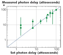
Remarkably, it is possible to accurately estimate path length changes with uncertainties that are on the order of a single nanometer (or approximately a few attoseconds for propagation in air), demonstrating improvement over similar experimental setups by more than a factor of 100 (see Fig. 2). The procedure has been tested over several piezo-delay stage displacements within the range of 0.5 to 30 nm, and the estimated shifts returned in the experiment are consistently accurate.This scheme can be enhanced further by tailoring the HOM dip to this specific task. The dip could be made narrower or be designed to have smaller features to increase the Fisher information, resulting in higher measurement precision. With the high-efficiency photon-pair sources and detectors currently available, the same level of precision can be achieved in just a few minutes, or potentially even less.
The length scales that can now be measured, combined with the inherent stability of HOM interferometers, makes this kind of procedure suitable for challenging bioimaging and sensing applications such as the direct detection of single strands of DNA and cell membranes that have nanometer-level thicknesses. Consequently, these demonstrations introduce HOM quantum interference to the world of high-precision metrology.
REFERENCES
1. C. K. Hong et al., Phys. Rev. Lett., 59, 18, 2044–2046 (1987).
2. D. Branning et al., Phys. Rev. A: At. Mol. Opt. Phys., 62, 6, 063808–063801 (2000).
3. Y. H. Shih and C. O. Alley, Phys. Rev. Lett., 61, 26, 2921–2924 (1988).
4. D. Giovannini et al., Science, 347, 6224, 857–860 (2015).
5. A. Lyons et al., Optica, 5, 6, 682 (2018).
6. A. Lyons et al., Sci. Adv., 4, 5, 1–8 (May 4, 2018).
Ashley Lyons is research associate and Daniele Faccio is group leader, both in the Extreme Light Group at the University of Glasgow, Glasgow, Scotland; e-mail: [email protected]; www.gla.ac.uk.

