ALEX PASQUARELLA, DAVID VIGLIONE, and STEPHEN PASQUARELLA
From laser scanning mirrors to micropositioning slides, electromechanical actuators are used in many areas of optical design. In the case of optical shutters, actuator technology is often shrouded by other features and specifications. As the "engine" of a shutter device, the actuator determines the shutter's overall reliability and performance, making it a critical component within any shutter device. This article offers information to help guide a potential user to better identify which shutter device will operate and fit best in a particular shutter application.
Although traditional solenoids are well suited for many purposes, including electromechanical relays, such an actuator does not provide a uniform force throughout its stroke, making this technology less than ideal for use in optical and laser shutters. For this reason, Vincent Associates has developed novel, high-performance actuator designs for all its Uniblitz shutter devices.
The constant-force linear actuator
A standard solenoid actuator is constructed and designed with a cylindrical coil of wire of which a metal armature can move freely through the central part of the coil. This armature is acted upon by the field produced in the core. A standard tubular solenoid is often used in shutter design. The key advantage of such a device is its inherent power-to-size ratio.
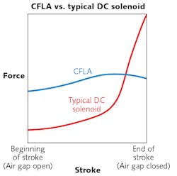
The disadvantage is that the forces provided tend to peak at the trailing edge of the solenoid's stroke. The flux and the output force both increase at increasing rates—the force exerted by the solenoid at the end of the stroke is usually several times the force available at the start (see Fig. 1).
As compared to the solenoid, the constant-force linear actuator (CFLA) produces greater leverage at the beginning of the actuation and remains relatively constant toward the end of the stroke. The net result is a work function that is evenly spread throughout the actuation of the shutter.
How the CFLA works
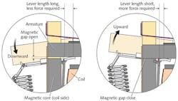
In the CFLA, the pull is more nearly linear as a function of its position and higher at the onset of motion than that of the typical solenoid. This is an important feature in accelerating a load (such as a shutter blade). Since the force does not rise at the end of the stroke for the CFLA, there is less impact on the armature and more useful work is obtained. When the actuator coil is energized and the armature is pulled toward it, the point of contact between the armature and pivot mechanism changes, decreasing the length of the lever. The lever then requires increased forces to continue closing the gap between the armature and the coil. However, as the gap closes, the forces in the magnetic circuit are increasing, so these increasing forces coupled with the decreasing lever length provide a net constant force to the load—the load being the shutter-blade mechanism.
The CFLA is configured for single-, dual-, and multi-bladed rotary drive ring-type shutter devices. The intricate nature of the design is deceiving, as the forces developed in the actuator and pivot exceed 100 psi (see Fig. 2). Use of the CFLA use extends beyond conventional shutter applications—it has been used as a stand-alone actuator within various applications. Its power and speed can be used in situations where a load needs to move a short distance very quickly, such as in a line-scan camera where only a small movement is required to expose a single slit very rapidly.Another important feature of this device is its fast release. Typical electromagnetic devices are inherently slow at releasing, since the force in a closed gap is extremely high. In these devices, the opposing mechanical force to release is relatively weak and a finite time is required for the magnetic field to fall to a value where the mechanical return force provides a closing motion. In the CFLA, the inverse of the mechanical advantage at the opening provides a fast closing as well by allowing the lever to break the gap and let the spring action close the device very quickly.
Non-Contact Activation System
As the industry evolved, new technological requirements for optical and laser shutter systems began to emerge, many of which demanding extremely long shutter lifetimes, streamlined form factors, and new operational features. Building upon the performance and reliability of the constant-force linear actuator, a more efficient, simpler shutter and actuator mechanism that we call the Non-Contact Activation System (N-CAS) was created.
To achieve long lifetimes, N-CAS shutter devices are constructed with few moving parts. Fewer moving parts not only leads to less wear, but also allows for the use of a simpler shutter controller circuit, further lowering costs and allowing for ease of integration into original equipment manufacturing (OEM) applications.
The N-CAS introduced a bi-stable capability that is not easily produced within the CFLA or a traditional solenoid-driven device. Optical systems that require a shutter device to be held in the open/active state for long periods of time benefit greatly from a bi-stable feature since heat produced in the actuator coil is eliminated. Power is only required to change the state of an N-CAS shutter-no hold voltage is necessary.
How the N-CAS works
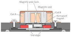
Two actuator coils (coil A and coil B in Fig. 3) are positioned side-by-side and connected by a shared magnetic core, creating two pole faces. A permanent magnet is mechanically coupled to the shutter blades, and is constrained to move from one pole face to the other.To open the shutter, both coils are energized, each generating an opposite magnetic field. With one coil repelling the permanent magnet and the other attracting it, the magnet is propelled from one core position to the other, thereby actuating the shutter. As the magnet comes into alignment with the attracting core, the motion of the magnet is arrested and stopped so as to "lock" the shutter blades in the open position. De-energizing both coils will allow the shutter blades to remain in an open position until the current applied to the coils is reversed to close the shutter. In the CFLA design, the actuator is mechanically coupled to the mechanical blades' movement. In this design, the actuator is coupled magnetically to the blades, thus limiting wear in the actuator itself.
The DSS system
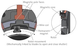
Advances in various imaging systems prompted the demand for shutter devices with extremely slim profiles and compact form factors. By referencing the thin designs of shutters utilizing the Non-Contact Activation System, such as Uniblitz NS series shutters, our design-scalable shutter (DSS) system took the design a step further by integrating the coil internally. This enables a shutter with two completely flat sides, with no protruding components that prevent the shutter from fitting into a critical envelope. The level of reliability as a result of these factors is high: DSS shutter devices can achieve cycles in the tens of millions.
A magnetic core creates two pole faces (see Fig. 4). A permanent magnet is mechanically coupled to the shutter blades and is constrained to move from one pole face to the other. The permanent magnet is positioned in between the core's poles, with the magnet's pole facing the core and magnetically attracted to the closest pole face.When the coil is activated, the pole face nearest to the magnet becomes a repelling force, while the opposite pole attracts the magnet. The magnet is propelled from one core position to the other, thereby actuating the shutter. As the magnet comes into alignment with the attracting core, the motion of the magnet is arrested and stopped so as to "lock" the shutter blades in the open position. De-energizing the coil will allow the shutter blades to remain in an open position until the current applied to the coil is reversed to close the shutter. While the fundamental theory of the DSS actuator is very similar to the N-CAS design, in the DSS actuator, the core and moving magnet are aligned in the same plane, allowing for more compact and efficient movement.
While actuator technology has evolved over the years, the fundamental function of actuators, with regard to optical and laser shutters, has remained the same: To repeatedly open and close a shutter, given a certain exposure and frequency of operation. Various operational factors have prompted an array of actuator configurations, thereby allowing users to determine which actuator, and associated shutter device, will properly suit their system. With this in mind, each of these actuator types provides its own particular strengths and advantages, despite the fact that all of them achieve very high speeds and lifetimes.
Alex Pasquarella ([email protected]) is the marketing specialist, Dave Viglione ([email protected]) is the engineering director, and Stephen Pasquarella ([email protected]) is the president of Vincent Associates, Rochester, NY; https://www.uniblitz.com.
For More Information
J. Evans and A. Vincent, High Performance Shutters (1969).
D. Viglione and S. T. Pasquarella, "Non-Contact Shutter Activation System and Method," VA, Inc. (assignee), Patent 7,513,702 (Apr. 7, 2009).
D. Viglione and S. T. Pasquarella, "Shutter Assembly with Drive Ring-Mounted Magnet," VA, Inc. (assignee), Patent 8,313,255 (Nov. 20, 2012).
A. W. Vincent, "Constant Force Electromechanical Actuator," VA, Inc. (assignee), Patent 3,427,576 (Feb. 11, 1969).


