MIKE ALLEN and PAUL SHARMAN
The term photodiode array refers to a detector with multiple discrete elements, each acting as separate p-n photodiodes. In some applications, most notably in military and aerospace, an array may be assembled from several individually fabricated detectors, but most of the time an array is a single monolithic structure. The majority of arrays are based on silicon, for cost and wavelength reasons, but they are also available in other semiconductor materials.
In a typical photodiode array structure each detector element consists of a p-n junction formed by standard planar diffusion methods. All the elements share a common cathode, which is a metallized back layer on the chip. The signal is read out from each element by a segmented front-side anode, consisting of a tiny wirebond pad.
Most applications for photodiode arrays involve OEM integration and utilize custom designed arrays. Nearly all these arrays fall into three basic formats: bi-cells, quad cells, and linear arrays. The linear arrays typically contain 1024 elements or less. For these smaller formats, a photodiode array generally offers greater system simplicity than a charge-coupled device (CCD) because there is no need for clocking signals and generating gate voltages. In addition, photodiode pixels can be individually read out without perturbing other pixels, unlike a CCD. For imaging applications requiring extended two-dimensional (2-D) arrays, however, the CCD is nearly always preferred because each photodiode element requires a separate lead and its own TIA (transimpedance amplifier), which is not manageable for large extended arrays.
In terms of performance, photodiode arrays offer all the advantages and flexibility of single-element photodiodes. They can be optimized for high sensitivity, by increasing the thickness of the active region, or optimized for speed, by decreasing device thickness. For "generic" devices, typical responsivity is up to 0.65 A/W. Silicon photodiodes also offer impressive linearity: as high as eight decades of linear response. Moreover, new technology enables efficient blocking of out-of-pixel detection, which could otherwise lower the effective spatial resolution (see "Novel masking process enhances array performance"). In addition, photodiode-array performance does not deteriorate over time, unlike devices such as photomultipliers, which are based on vacuum tubes. And like other semiconductor devices, photodiode arrays can be reliably and consistently produced in high volume, making them particularly attractive to OEMs.
The flexibility, reliability, and cost-effectiveness of photodiode arrays have taken these devices into an incredibly diverse range of applications, from NASA satellites to clinical lab tests. To understand the broad utility of photodiode arrays, it is useful to examine several applications.
X-ray baggage scanners
Ever wondered what is happening while you're waiting for your bag to pass through the airport x-ray scanner and the operator is intently studying the system's CRT monitor? Chances are the operator is toggling between hard and soft x-ray images of your luggage to compare these images and look for potential explosives and/or weapons. This simultaneous dual imaging is possible thanks to a novel photodiode array implementation originally patented by Lunar Radiation (Madison, WI).
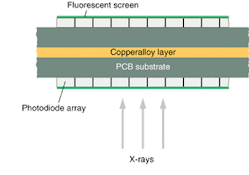
In a typical system a fluorescent screen is epoxied onto the front surface of a 16-element linear array, which is rear-side mounted onto a PCB. This screen emits near infrared (IR) light when irradiated by x-rays. Two of these units are bonded together back-to-back with a copper alloy layer sandwiched between them (see Fig. 1). These double-sided modules are typically about 1 in. long. The baggage detector contains a long row of these modules butted together to make a double-sided linear-array detector spanning the entire width of the baggage conveyor belt. An x-ray transmission image is built up as a sequence of line images as the bags are rapidly stepped between the x-ray source and array detector, both of which are stationary.The front-side photodiode array detects a combination of soft and hard x-ray images, depending on the sensitivity of the fluorescent screen. The copper alloy layer serves to absorb much of the remaining soft x-rays. The "back-side" fluorescent screen thus is exposed mostly to the hard x-rays. Comparison of the two images acts as a dual-wavelength x-ray spectral imager. Certain explosives and metals are readily highlighted by intensity differences in the two images.
Position encoders
Automated remotely controlled motion is used in a wide range of applications, from moving the flaps on an airplane wing, to precision motion in a CNC machine. The majority of these applications use some type of encoder to provide real-time feedback on this motion. There are two classes of encoders, providing either absolute or relative position information, and the majority of them are based on some type of optical technique with a photodiode array.
The most basic encoder design is a rotary encoder utilizing a single disk. This glass or metal disk has a series of radial slits machined (or masked) around it with a very uniform spacing. In the simplest configuration, the edge of the disk is placed between a light-emitting-diode (LED) source and a photodiode. As the slits cross the light path during rotation, the photodiode generates a corresponding sequence of signal pulses. These encoders are commonly placed on the drive shafts or screws used to cause the motion so they provide direct feedback.
Higher resolution can be obtained with multiple disks or with a single disk with concentric rings of slits with each ring having a slightly different pitch (angular spacing) in an optical analogy of a Vernier scale measurement. A multi-element linear photodiode array is positioned behind the disks with each element sensing light from a specific ring of slits. Again the light source is an LED. A simple signal processor combines the signals and thereby determines the precise amount of rotation that has occurred.
A more ingenious encoder design is the digital encoder, which also uses a linear photodiode array. Here the rotating disk contains concentric circles of small holes. The hole patterns are chosen so that at each position (minimum resolution specified for a particular encoder) of the encoder disk, there is a unique sequence of array elements that are "light" or "dark." Thus, each position is read as a binary sequence of '1's and '0's, making this device fairly impervious to signal noise or drifts.
Particle measurement and counting systems
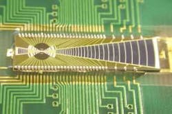
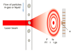
There are many applications for measuring and/or counting particles, such as measuring dust levels in clean-room environments, or looking at liquid suspensions such as inks or blood. Typical measurements are on the number of particles per unit volume or the particle-size distribution. The most common particle-measurement systems rely on Fraunhofer diffraction. The particles are forced to flow in a linear tube or stream (see Fig. 2). A low-power laser beam is directed through this flow at normal incidence. Forward diffracted light is then detected by a photodiode array.Every time a particle crosses the path of the laser beam, it causes the laser beam to be diffracted into a series of concentric cones—at any given distance the pattern appears as a series of circles with the bright undiffracted beam at the center. Counting these events yields the number of particles. The typical array for this type of instrument is a linear array containing up to 64 elements. Diffraction theory dictates that the light intensity decreases toward the edges of the diffraction pattern (that is, in the larger rings). But accurate particle-size determination requires quantitative intensity measurement of as much of the pattern as possible. For this reason the array has a unique shape with the pixel dimension increasing away from the center of the array (see photo at top of this page). In addition, to avoid saturation or damage due to the high intensity of the undiffracted beam, the center of the array is blocked using a metallized overcoat.
Smart weapons
With the military activity in Afghanistan and the possibility of war in Iraq, smart weapons are once again topical. Collectively, smart weapons represent one of the biggest applications for photodiode arrays. The simplest, most widely used example is the guided bomb relying on a laser target designator. Here a near-IR laser beam is directed at the target. Optics in the nose of the bomb image the target on to a quad cell through a bandpass filter at the laser wavelength (usually Nd:YAG at 1064 nm). A smart circuit in the bomb uses the photodiode signals as feedback to control directional vanes that adjust the flight trajectory. Specifically, the flight is adjusted so as to null the signal difference between diagonal pairs of elements, thereby ensuring the bomb is directed precisely at the laser spot. This basic system is very flexible and economical, given that the laser is not sacrificed as part of the bomb. The laser beam can be mounted in the launch platform (tank or plane) or directed from a third-party platform such as covert personnel on the ground.
Mike Allen is director of sales and Paul Sharman is director of operations at Advanced Photonix, 1240 Avenida Acaso, Camarillo, CA 93012; e-mail: [email protected].


