WILLIAM S. GORNALL
Interferometers are optical instruments that use the interference of light to evaluate surfaces, measure distance, or perform spectral analysis and wavelength measurement. For many years, researchers involved in laser spectroscopy have performed high-resolution spectral analysis with Fabry-Perot interferometers and wavelength measurements with Michelson interferometers. Now, two rapidly growing fields, laser radar (lidar) and dense wavelength-division multiplexing (DWDM), are putting new demands on the way we use interferometry to support the special measurement requirements of these applications.
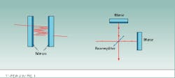
The two most common types of interferometers are the Fabry-Perot and Michelson designs. The designs differ, but both instruments can be used for either spectral analysis or wavelength measurement. A plane-mirror Fabry-Perot interferometer consists of two flat mirrors that face each other to form a resonant cavity (see Fig. 1). Light enters the cavity through one slightly transmitting mirror and undergoes many reflections. The reflected beams interfere to produce sharp fringes at certain angles in the transmitted field. The relationship between the wavelength l, the mirror spacing d, and the angle of incidence q that produces a transmitted fringe is given by
m l = 2nd cosq [1]
where m is an integer denoting the order of the interference fringe, and n is the refractive index of the medium between the mirrors.
Scanning Fabry-Perot interferometers can perform spectral analysis of the output beams of continuous-wave (CW) lasers. The beam is introduced into the cavity, and the mirror spacing is changed by moving one mirror with a piezoelectric scanner. The transmitted intensity is a series of peaks representing spectral components of the laser at different wavelengths.
A Michelson interferometer consists of a 50/50 beamsplitter that divides an incident beam along two orthogonal paths, or arms. Reflecting mirrors at the end of each arm return the beams back to the beamsplitter, where they are recombined in the exit beam. If the end mirror on one arm of the interferometer moves to change the optical-path difference between the two beams, the beams interfere to form a sinusoidally varying intensity in the exit field.
If the wavelength of incident light is known, this technique can be used to measure mirror displacement. Conversely, if the displacement is known, the interferometer can measure laser wavelength. The transmitted intensity pattern displays one complete cycle (light to dark) for each increment of optical-path difference equivalent to one wavelength of the incident light. The number of cycles introduced into the transmitted intensity pattern by displacing the mirror a known amount yields the illumination wavelength. The Michelson interferometer can thus act as a simple CW laser-wavelength meter.
Spectral analysis for lidar
Lidar is a laser-radar-based technique that can monitor aerosols in the atmosphere. A laser transmitter sends out a pulse of laser light toward a target, and a receiver captures the backscattered signal. The time delay between the outgoing pulse and the detection of the return and the spectral content of the backscattered light provide information about the constituents of the medium traversed.
The pulse durations involved in lidar, typically 10 ns, are too short to permit the use of scanning interferometers for spectral analysis of the laser source. A plane-mirror Fabry-Perot interferometer can, however, be operated in a static configuration. Such fixed interferometers are often referred to as etalons. Fabry-Perot etalons have parallel reflecting surfaces and, when illuminated with diverging light, produce a characteristic bulls-eye fringe pattern corresponding to different angles of incidence. Fizeau etalons, similar in design to Fabry-Perot etalons, feature slightly wedged reflecting surfaces. The transmission of a broad collimated laser beam produces equally spaced, straight-line fringes at those positions along the wedge where d satisfies Eq. 1.
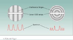
With appropriate optics to diverge or expand the incident laser beam as it passes into the optical cavity, the resultant fringe pattern from a static etalon is spread out in space. A linear charge-coupled-device (CCD) camera positioned across the fringes records the pattern, which is digitized and analyzed to construct the interferometer spectrum (see Fig. 2). The output from the Fizeau etalon is typically simpler to analyze because the fringes are equally separated, but the line shapes become asymmetric for large mirror separations. The Fabry-Perot bulls-eye pattern has better-shaped fringes but they are not equally spaced. This is not a problem, however—once the CCD camera image is digitized in a computer, the nonlinear fringe spacing can be corrected.The Resolver (Burleigh Instruments Inc.; Fishers, NY) incorporates either a Fabry-Perot or a Fizeau etalon to produce a spectrum of an individual pulse from a lidar laser transmitter. An embedded computer in the instrument generates the spectral display and calculates spectral parameters such as peak spacings and linewidths in real time.
Etalon type and size are chosen to match the spectral breadth of the laser. With a 20-mm-thick Fabry-Perot etalon, for example, the instrument can analyze a pulse for spectral composition and linewidth to an instrumental resolution of 100 MHz. This is approximately the transform limit for a 10-ns pulse, which means the instrument is capable of resolving any spectral mode structure in the types of pulsed laser beams used for lidar. Shorter etalons can be substituted if necessary to suit the spectral profile of lasers with broader emission bandwidth.
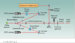
Differential absorption lidar is a specialized technique for determining gas concentrations by detection of absorption features (see Laser Focus World, April 1997, p. 95). The laser transmitter must be accurately tuned to a specific absorption line to permit detection of a particular molecule of interest. To monitor the absolute wavelength of a pulsed laser source, both Fizeau and Fabry-Perot etalons are used, as in the two-etalon Pulsed Wavemeter (Burleigh Instruments; see Fig. 3). Multiple etalons are required to achieve high accuracy, and the optical thickness of each etalon must be accurately calibrated.A beamsplitter divides the test pulse into two optical paths, one passing through a thin Fizeau etalon and the other passing through a thick Fabry-Perot etalon. Charge-coupled-device cameras on each path simultaneously capture the fringe patterns. A pulse detector registers that a laser pulse has entered the instrument and triggers the wavelength computation.
The data from the Fizeau etalon provide wavelength measurement to within approximately 100 parts per million (ppm). This information is then used to establish the order number for the fringe pattern of the Fabry-Perot etalon, allowing a further computation that increases the accuracy of the wavelength measurement to 1 ppm. Between measurements, shutters block the input beam and introduce the beam from a helium-neon (HeNe) reference laser to verify the calibration of the etalon spacings.
Wavelength meters based on fixed etalons are now widely used for other pulsed-laser applications such as nonlinear spectroscopy, multiphoton ionization, laser-induced florescence, and laser isotope separation, in which the absolute wavelength of a single laser pulse must be determined.
Absolute wavelength measurement
Dense-wavelength-division-multiplexing (DWDM) systems use CW diode lasers to generate signals at multiple wavelengths within the gain bandwidth of erbium-doped fiber amplifiers (1530 to 1570 nm). The standard proposed to the International Telecommunications Union (Arlington, VA) specifies frequencies spaced by 100 GHz (about 0.8 nm) above and below 193.1 THz (1552.5 nm). Each wavelength must be accurately set and maintained to within ۪.05 nm on this standard wavelength grid.
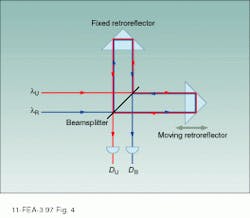
The best way to measure the absolute wavelength of each laser to this accuracy is with a wavelength meter incorporating a scanning Michelson interferometer that compares the wavelength of an unknown laser lU to that of a known reference laser lR. In a typical optical configuration, corner-cube retroreflectors separate the outgoing and return beams in each arm of the interferometer (see Fig. 4). In this way, the unknown laser beam and the reference laser beam can be directed along exactly the same path in opposite directions and the resultant interference pattern captured on photodetectors for the reference beam (DR) and the unknown beam (DU).If the reference beam is provided by a HeNe laser with a known wavelength, the unknown laser wavelength can be determined from the equation:
lU = (NR/NU) (nU/nR) lR [2]
where NR/NU is the ratio of the number of fringes counted from detectors DR and DU, and nU/nR is the ratio of the refractive index of air at the unknown and reference wavelengths. By using long scans or subdividing the fringes, the unknown laser wavelength can be determined to an accuracy nearly equivalent to that of the reference laser, typically ۫ ppm or better.
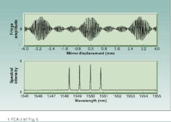
This technique is very useful for measuring the absolute wavelength and testing the wavelength stability of the DWDM diode-laser sources, but it has the limitation of only measuring single wavelengths. Once all wavelengths are combined by the DWDM system in a single fiber, a means of accurately measuring multiple wavelengths simultaneously is needed. The Michelson configuration discussed above can also perform this task. The fringe pattern for the test beam, detected by DU, can be sampled at regular intervals derived from the periodicity of the reference laser fringe pattern measured at DR(see Fig. 5). The Fourier transform of this data yields the complete spectrum of the DWDM transmission. The sampling interval is calibrated by the known wavelength of the reference laser, so the absolute wavelength of each component in the spectrum can be accurately determined. With this technique it is possible to determine the relative intensity and measure the wavelengths of all the components in the DWDM spectrum as they exist in the fiberoptic cable, to an accuracy of a few picometers.Lidar and DWDM are only two applications setting new requirements for high-resolution spectral analysis and accurate wavelength measurement. Because lasers are highly coherent light sources, interferometry will always play a dominant role in measurement and analysis for laser-based systems, and engineers will continue to find inventive ways to apply the fundamental techniques.
William S. Gornall is vice president of technology at Burleigh Instruments Inc., Burleigh Park, Fishers, NY 14453; e-mail: [email protected].
