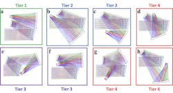
Lenses and mirrors with freeform surfaces enable optical designers to create, for some purposes, optical devices that are lighter, more compact, and more effective than conventional designs using spherical or even rotationally symmetric aspherical optics.
However, until now, determining which freeform surfaces will work best (if at all) in a given optical configuration has been a time-consuming and often expensive process of trial and error.
Now, in a paper in Nature Communications, lead author Aaron Bauer, a senior research engineer at the University of Rochester's Center for Freeform Optics (CeFO), combines theory and practice in a step-by-step method that eliminates much of the guesswork.1
"Aaron has developed a process to design with freeform surfaces that can be applied very generally," says coauthor Jannick Rolland, CeFO director and Brian F. Thompson Professor of Optical Engineering. "It's really beautiful, and even at times feels like magic."
She believes the findings will help accelerate the adoption of freeform optics in industry. "People will no longer say 'Oh, it's too expensive to build with freeform optics,'" she says. "Because now you can make something that may cost a tenth of what it would have cost otherwise."
Laying the groundwork
Traditionally, optical designers have relied on rotationally symmetric optical surfaces in their designs, because their design and manufacture is relatively straightforward. Within the last 20 years, advances in high-speed micromilling, computer-controlled lens polishing, and ion-beam etching, among other technologies, have made asymmetric freeform surfaces more feasible.
In a paper in 2014, Kyle Fuerschbach, a former member of the Rolland Lab, laid the theoretical framework for freeform aberrations theory. "But we still didn’t have a systematic process to design with that theory," Rolland says.
Bauer, in the meantime, was working alongside Fuerschbach, designing a head-worn display using freeform surfaces.
"I noticed that there were very common patterns of aberrations that were always popping up, and limiting my system from going any further," Bauer says. Moreover, "those patterns of aberration matched the ones that Kyle predicted would be corrected by freeform surfaces. So, I put two and two together."
The method he came up with starts with the initial folding geometry (alignment of mirrors and lenses) contemplated for a design, and then, based on an analysis of the various aberrations produced by that alignment, predicts whether freeform surfaces could minimize those aberrations and, if so, which freeform surfaces should be used for maximum effect.
"Freeform surfaces are not a universal solution for correcting every aberration," Bauer notes. "So, what our method does is to allow designers to analyze all of these geometries ahead of time, in order to predict whether or not there would be a good solution."
That's far better than the brute-force approach where "people heuristically try various freeform surfaces into a design," Rolland says. "Even if it eventually works, you could end up with a system where the departure of the surfaces are much larger than they would be otherwise, because all those freeform surfaces may be fighting each other. And if it does not work, there is nowhere go as a designer."
By using Bauer's method instead, she says, "you will be able to design something that is a lot simpler, and that will be easier to manufacture and test. Furthermore, the method will quickly and unequivocally provide insight into why a given geometry might be intrinsically limited, which is essential for designers."
Eric Schiesser, a PhD student in the Rolland lab, also contributed to the paper.
Source: http://www.rochester.edu/newscenter/freeform-optics-new-method-lenses-316222/
REFERENCE:
1. Aaron Bauer et al., Nature Communications (2018); doi: 10.1038/s41467-018-04186-9.

