FETAH BENABID, FRANÇOIS COUNY, PHILIP S. LIGHT, AND PETER JOHN ROBERTS
The development of nonlinear and quantum optics applications based on gas-phase materials has been impeded by the lack of a suitable technology for creating devices that guide light in a single transverse mode over long interaction lengths, while still offering a high level of integration in a practical and compact setup or device. This constraint meant that gas-phase materials were overlooked in favor of their solid-phase counterpartseven for applications in which the former outperformed the latter. But the development over the past decade of hollow-core photonic-crystal fiber (HC-PCF) has fulfilled this longstanding wish of transporting tightly focused laser beams over long distances without the constraints of diffraction (see www.laserfocusworld.com/articles/328524).
The ability of today’s state-of-the-art HC-PCF to confine gases and light together at mode areas of several square microns while maintaining interaction over lengths that exceed several hundred meters has created a new paradigm in gas-laser-related applications. This has been illustrated in recent years by strong nonlinear effects such as stimulated Raman scattering, electromagnetically induced transparency, and saturable absorption in gas-filled HC-PCF at extremely low light levels.
In synergy with these demonstrations, our understanding of the photonic-guidance mechanism of these fibers led to the proposal of the photonic tight-binding model to explain the genesis of photonic bandgap in triangular-lattice HC-PCF and to the quasi-bound photonic state in a continuum to elucidate the guidance in Kagome-lattice HC-PCF. Furthermore, gas-filled HC-PCF is now available in a highly compact and integrable formthanks to the development of photonic microcells that consist of gas-filled HC-PCF hermetically spliced to conventional all-solid optical fiberspaving the way for a new breed of gas-phase photonic materials.1, 2
Two guidance mechanisms
Since the first demonstration of air guidance using HC-PCF, two types of this fiber have emerged and been successfully deployed in nonlinear and quantum optics applications: the triangular-lattice HC-PCF and the Kagome-lattice HC-PCF. These fibers exhibit complementary optical properties and radically different guidance mechanisms.
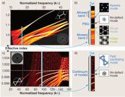
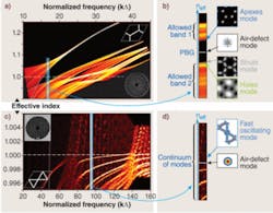
The triangular-lattice HC-PCF, in which cladding is formed by a triangular arrangement of air holes surrounding the core, guides light in a hollow core via an out-of-plane photonic-bandgap mechanism (see Fig. 1). The absence of cladding modes at the frequencies and indices of the core-guided modes also means that the density of photonic states is zero. Recent studies show that the formation of the photonic bandgap in triangular HC-PCF is explained by the photonic analog of the tight-binding model in solid-state physics.3 The work identified the air holes, the glass interstitial apices, and the glass struts to be the three structural features in the photonic structure responsible for the formation of the allowed photonic states. The photonic bandgap in these fibers lies between the photonic band of the interstitial apices and a band formed by the overlap of photonic bands generated from the silica struts and the air holes, respectively. As the density of photonic states falls to zero within the photonic bandgap, light is effectively trapped inside the micrometer-scale core defect and for a bandwidth of approximately 50 THz can be guided over kilometer-long distances with losses on the order of a few decibels per kilometer.
The second type of fiber is the Kagome-lattice HC-PCF, which is formed by tessellated star-of-David patterns surrounding the core defect. The fiber guides light via a guidance mechanism that differs from photonic bandgap because the core-guidance frequencies and indices are such that the photonic structure exhibits a nonzero density of photonic states. Instead, the defect core mode cohabitates with a continuum of cladding modes akin to the Von-Neumann-Wigner quasi-bound states in a continuum.4 Such inhibited coupling between the core mode and the cladding modes is explained by the fast transverse oscillations of the cladding modes constituting the continuum. In addition to this new guidance mechanism, the fiber guides light over a much broader bandwidth (more than 20 times larger than photonic-bandgap HC-PCF), but with a loss figure not much less than 1 dB/m. These antithetical optical properties mean that fibers can be tailor-made for a particular nonlinear application as illustrated in a subwatt continuous Raman laser developed by our group in Bath using an ultra-low-loss photonic-bandgap HC-PCF and the generation of an extremely broad frequency comb using the Kagome fiber.
Ultracompact photonic microcells
The first demonstration of gas-laser interaction in HC-PCF confirmed the anticipated potential of these fibers.5 Since then, huge efforts have been made to render this new photonic component compact and integrable, resulting in the development of a photonic microcell.
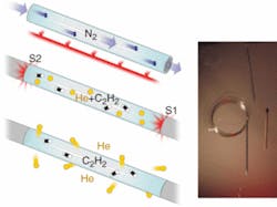
A photonic microcell consists of a length of HC-PCF filled with a given active gas and hermetically sealed to a solid optical fiber with a minimum of splice loss (see Fig. 2). Originally, the technique of the photonic microcell was limited to relatively high pressure because of the exposure to the atmospheric environment during the splicing process. Recently, this limit has been lifted, thanks to a new technique that enables fabrication of the microcells with extremely low pressure while keeping the optical insertion loss to a minimum. The new technique relies on the permeability of helium in silica and allows the creation of photonic microcells at micro-Torrs of pressure.
Nonlinear applications
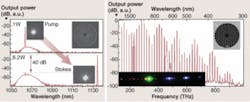
The exceptional nonlinear conversion efficiency achieved in HC-PCFthanks to the combination of small effective area and ultralong interaction lengthhas already been demonstrated by the millionfold reduction of threshold laser power for the observation of stimulated Raman scattering in the pulsed regime. As a matter of fact, the fiber has proved to be the perfect test bed for fundamental studies of the Raman effect in the ultrahigh Raman gain regime, while still offering an ultracompact package. Photonic microcells can also convert 99.99% of a continuous-wave input laser beam into a Raman Stokes radiation at subwatt power threshold and with 50% efficiency (see Fig. 3).6
The ultrabroadband guidance property of Kagome fiber has also been put to use in the generation of multi-octave frequency combs with kilowatt peak power thresholds, spanning nearly 1000 THz and close to generating ultrashort pulses down to the attosecond levela figure so far accessible only by high-harmonic generation using high-power lasers. The flexibility of the generated spectrum and the compact design of the fiber gas cell mean that portable optical waveform synthesis is within reach.
Quantum-optics applications
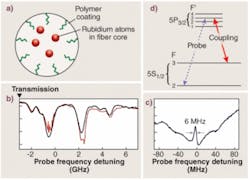
Among the successful demonstrations of HC-PCF in quantum optics and laser metrology are laser stabilization and electromagnetically induced transparency using acetylene molecules confined in the core of these fibers (see Fig. 4).7, 8 These results show that strong signal-to-noise ratios and huge nonlinearities can be obtained despite the small dipole strengths involved. Consequently, the combination of alkali metals such as rubidium and cesium and HC-PCF hold the promise of exciting coherent phenomena with a single photon. However, the confined geometry of HC-PCF and extreme physiochemical reactivity of the alkali metal vapors renders the loading process challenging. Also the strong coherence dephasing due to the collisions of vapor atoms with the core wall cast doubt on the suitability of HC-PCF for coherent optics applications.
Fortunately, recent results show that coating the fiber core with a polymer layer not only reduces the dephasing effect of collisions, but could also act as an atomic vapor source via light-induced atomic desorption.9, 10 Using this method, generation of electromagnetically induced transparency can be achieved in a rubidium-filled HC-PCF with a linewidth much lower than that set by the collision rate with the core wall.
REFERENCES:
1. F. Benabid et al., Nature 434, 488 (2005).
2. P.S. Light et al., Optics Lett. 31, 2538 (2006).
3. F. Couny et al., Optics Express 15, 325 (2007).
4. F. Couny et al., Science 318 (2007).
5. F. Benabid et al., Science 298, 399 (2002).
6. F. Couny et al., Phy. Rev. Lett. 99, 143903 (2007).
7. S. Ghosh et al., Phys. Rev. Lett. 94, 093902 (2005).
8. F. Benabid et al., Optics Express 13, 5694 (2005).
9. P.S. Light et al., Optics Lett. 32, 1323 (2007).
10. S. Ghosh et al., Phys. Rev. Lett. 97, 023603 (2006).
Tell us what you think about this article. Send an e-mail to [email protected].
FETAH BENABID is advanced fellow and principal investigator, and FRANÇOIS COUNY and PHILIP S. LIGHT are researchers in the physics department at the University of Bath, Claverton Down, BA27AY Bath, England; e-mail: [email protected]; www.bath.ac.uk. PETER JOHN ROBERTS is a professor in the DTU Fotonik department at the Technical University of Denmark, DK-2800 Lyngby, Denmark; www.dtu.dk.
