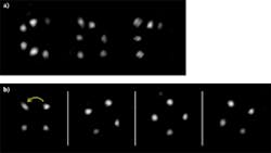
Conventionally, an optical fiber carrying continuous light at a single wavelength transmits no data (other than that the light source is on). Amplitude modulation is what carries the information; wavelength-division multiplexing (using more than one wavelength at a time) can further boost the data rate. However, there is another way to transmit information over a fiber, and that is by exploiting its spatial modes. In one very interesting approach developed by Roberto Di Leonardo and Silvio Bianchi at the Università di Roma La Sapienza (Rome, Italy), the information is in the form of a controllable pattern of light spots.
The researchers use a spatial light modulator (SLM) to modify a multimode fiber's incoming beam; the result is that the fiber's output consists of a hologram made up of one or more spots, each with an independently controllable position.1 The concept could someday be useful in endomicroscopy, allowing scanning of a specimen through a section of fiber encased in a thin rigid needle.
Direct-search algorithm
The researchers use a large-mode-area fiber, which can transmit thousands of modes; with a 105 μm diameter core and a 0.22 numerical aperture, the chosen 2 m section of fiber carries on the order of 3770 modes. Laser light at 532 nm is expanded and collimated to fill the active area of a phase-only SLM with 1024 × 768 pixels. The light reflected from the SLM is focused onto a pinhole that passes only the first-order modulated beam, which is then refocused into the input end of the fiber.
At the other end of the fiber, exiting light is collimated, passed through a linear polarizer, and directed onto a CMOS camera. Without any phase modulation, the output looks like what one would expect: a speckle pattern. But the researchers apply an iterative direct-search algorithm, which starts out with a random phase iteration on the SLM but then uses a merit function to home in on the desired fiber output.
The algorithm maximizes the product of the desired spots' intensities, and converges on the desired solution after about 2500 iterations. The optimization takes about 10 minutes, limited by the data acquisition of the camera. However, once the phase modulation is determined, it can be used quickly at any time in the future, at least if the fiber length is unchanging enough in shape that it does not change the modes.
The peak intensity of a single optimized spot is about 35 times that of a speckle in the initial nonoptimized speckle pattern. When a multiple of spots is created, the intensity of each spot decreases, but the total light power (sum of all spot powers) increases slightly.
The setup is able to project holograms that are patterns of spots, which can be either static or moving images. The researchers have created a mathematical model of the process, allowing them to calculate the relative intensities of the spots in a two-spot pattern as a function of the phase modulation, which could be useful for modeling the intensity ratio for two superposed single traps in holographic optical tweezers.
"We're now working on the nanofabrication of micro-optics on the fiber tip to increase the numerical aperture of the outgoing light," says Di Leonardo. "That will allow both a higher resolution for microscopy application and the possibility of producing tighter focused spots for optical trapping."
Possible configurations for endomicroscopy could include one or more spots being scanned. "The easiest, although slowest, strategy would be that of scanning a single spot while simultaneously collecting fluorescent light through the same fiber," notes Di Leonardo.
REFERENCE
1. R. Di Leonardo and S. Bianchi, Opt. Exp., 19, 1 (Jan. 3, 2011).

