Mary Turner
In optical-analysis programs, an optimization process systematically varies system design parameters to reach specified performance metrics. While optical- or lens-design programs optimize imaging systems like lenses and telescopes, they are inappropriate for nonsequential applications, such as illumination systems.
An optimization process contains three integral components: a performance requirement or design goal specifying required system constraints; a set of design parameters, including some that can vary; and an appropriate optimization algorithm. A merit function comprising a set of rules or targets and constraints, which relate defined parameter values, specifies the performance goals. As system parameter values change, the merit function also changes. Optimization is effectively an attempt to solve for a merit function of zero, which indicates the software has achieved all targets without violating any constraints. In an n-dimensional solution space, a “local” minimum is the low point of each valley in solution space. The “global” minimum is the location in solution space with the absolute lowest merit function value.
Several techniques are available for optimizing imaging systems. Typically, a designer uses a predefined set of weighted targets that work with a specific optimization algorithm. Each target is a ray traced from specific locations in the system’s object space to specific locations in the entrance pupil or aperture stop, then through the system to the image surface. Available optimization techniques, usually based on damped least squares (DLS) or singular value decomposition (SVD), attempt to form a point image for each point in object space. Such techniques are best for finding the best solution in a local solution space.
Historically, optimization of illumination systems has proved to be a challenge. In illumination systems, there is no one set path that all rays must take. No pupils exist defining the valid energy region. Realistic extended sources cannot be well represented by a point-source approach. Most important, the design goal is a particular energy distribution, not imaging a point in object space to a point in image space.
Consider the simple example of an energy distribution on a surface some distance in front of a parabolic reflector having a source at its focus. Simple observation tells us that some energy reaching the surface comes directly from the source, never striking the parabola. The remaining energy exits the reflector in a pseudo-collimated fashion, assuming a sufficiently small source. One might think that this simple problem is a combination of two systems, each in itself, sequential. However further analysis shows that there are actually three ray paths through this system: the direct source to surface rays; rays that leave the source, hit the reflector, and travel to the surface; and another ray path that has light reflecting twice before reaching the wall, still maintaining its pseudo-collimation. The amount of energy in each path depends on the system’s shape factors, but a significant percentage of rays in the second path may be taking the third path. Additional complications arise in many illumination systems with faceted rather than continuous surfaces. Such surfaces can be parametrically defined using a CAD program, but they cannot be described using implicit or explicit polynomials commonly used to describe classical optical surfaces.
null
A range of techniques
General nonsequential optimization must be able to define any appropriate set of targets and constraints and to select an optimization technique that works within the actual topography of solution space. Although a particular optimization algorithm can perform very well within a given form of solution space, no algorithm works equally well over a wide range of optimization requirements. Designers need a range of optimization techniques, as well as the ability to define any complex targets and constraints for a wide range of performance goals. Typical goals might include total captured energy, illumination uniformity (in spatial, angular, or direction cosine space), or information based on scatter, diffraction, coherence, or any other measurable property. ASAP provides several optimization algorithms for sequential and nonsequential design. Available tools allow sorting of ray information in any manner necessary for defining any required optimization target. Optimization can be performed on any system parameter, including Bezier-based CAD surfaces.
Three algorithms available in ASAP can be used for optimization of nonimaging systems, including Brent’s method, for finding the minimum value one-dimensional solution space (only one variable), simulated annealing, which is useful for systems that have many closely spaced local minima, and downhill simplex, which is useful for finding a local minimum solution for situations having smooth and continuous solution space.
An important consideration involves selecting traced and analyzed rays. Imaging-system performance can be exactly characterized over several field locations and wavelengths by tracing a couple dozen rays. Fully sampling complex sources including LEDs or filament lamps requires thousands or even millions of rays. Similar sampling is necessary for all components, including faceted surfaces. Full analysis of automotive headlamps can take a day or longer. Therefore, to use optimization techniques effectively in illumination design, designers must carefully consider all aspects of each design task, looking for conditions including symmetries, angular and spatial dependencies, and others that can be exploited to reduce ray-tracing requirements.
An example
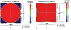
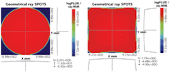
Consider a projection system. A visually uniform illumination pattern is required at the screen location. However, system efficiency can be improved when the output distribution conforms to the square or rectangular shape of the required distribution, rather than having the energy clipped by a rectangular mask. Although large numbers of rays will be needed for the final analysis, we can optimize the basic form with carefully selected rays that map an initial circular distribution to the desired form.
A Bezier patch was defined with the necessary size and shape for the reflecting optic. Variable parameters can include coordinates of the control points and the control weighting factors. Recognizing the system’s symmetric nature, we can further reduce the amount of ray tracing to those rays that simply map one quadrant of the screen.
Although this example uses a point source, the method also can be used for systems with larger sources and surfaces with greater complexity. Describing this surface with Bezier patches provides greater design freedom than using standard optical surface forms while providing a solution that can be exactly exported to a CAD manufacturing environment. This optimization was performed in this case by using three variables and targeting six rays (see figure). One million rays were used for the final analysis.
Mary Turner is the director of technical training at Breault Research Organization (BRO), 6400 E Grant Road, Suite 350, Tucson, AZ 85715; e-mail: [email protected]; www.breault.com.

