XAVIER LEVECQ
Today’s petawatt and terawatt class lasers are used in a variety of applications, from high-energy proton/electron beam generation for medical therapies to the study of laser/matter interaction and plasma creation. Although the theory behind the generation of these very high power levels has been around for many years, practical implementation on a broad scale was not possible for technical and practical reasons.
On the technical front, scientists were unable to grow the artificial crystals used in laser-beam amplification with sufficient optical quality on a consistent basis. In addition, as laser energy accumulates in these crystals, the thermal effects cause index variations that reduce optical quality. The cryogenic technologies commonly used today to cool the crystals had yet to be developed.
On the practical side, the ability to improve temporal response had to be addressed. This was only resolved through lengthy research that depended on solving the technical challenges.
The first step to opening up this field of research came in the early 1990s with the introduction of pulsed high-intensity lasers based on combining chirped-pulse amplification (CPA) with optical compression. This approach provided exceptional gains in power output without introducing the nonlinear effects that degrade beam quality during amplification and that cause damage to sensitive optical components. This advance made it possible to build petawatt and terawatt lasers small enough fit onto a few standard optical benches in a laboratory.
Once it became easy to build high-energy lasers in a laboratory, the challenge was to improve the focal spot of the beam. After all, the reason for building such high-intensity systems was to be able to focus extreme fluence, or intensity, onto the target. The ratio of beam power to the intensity at the target is given by:
where E is the energy per pulse of the laser, r the size of the focal spot and Δτ is the duration of the pulse. It is evident from this equation that the intensity at the focal point is linearly dependant on the energy and duration of the pulse, but it also has a quadratic dependence on the size of the focal spot. Hence, amplifying the beam was no longer enough and the quest to perfect the focal spot began.
The quality of the focal spot is a direct product of the amplification process. From stretchers and compressors, on to the amplifiers themselves, each step in the amplification chain introduces aberrations that degrade the beam quality. The secret of a well-focused beam is mastery of the beam’s wavefront quality.
Adaptive optics
Development of adaptive-optics technology originated with the defense industry but astronomers quickly recognized its potential to improve the vision of ground-based telescopes by compensating for the aberrations caused by turbulence in the Earth’s atmosphere. Since its original implementation, the technology has matured and new applications have emerged in free-space communication, ophthalmology, bioimaging and, of course, high-intensity laser systems.
An adaptive-optics system typically includes three elements: a measurement deviceusually a wavefront analyserfor monitoring the incident (incoming) wavefront; correction optics to compensate for the imperfections of the incident wavefront by creating an inverse wavefront form; and a command-and-control system to process the incident wavefront information and send commands to the correction optics.
Measurement is generally based on Hartmann and Shack-Hartmann wavefront analyzers, shearing interferometers, or wavefront curvature sensors. The Shack-Hartmann family of wavefront analyzers is by far the most common in adaptive optics. Invented in the early 1990s, they have become the device of choice because of their precision, reliability, and ease of use.
There are two primary technologies for wavefront correction: deformable mirrors and liquid-crystal valves. The latter are rarely used, however, because of their low damage threshold and relatively small effective pupil diameter. In reality, mirrors made of thin membranes that can be deformed by a matrix of actuators are used for adaptive optics in high-power lasers. Several technologies including bimorph or monomorph, stacked piezoelectric, electromagnetic, and mechanical assemblies are currently used to fabricate the actuator matrices. Most of the software used in adaptive optics is based on algorithms designed for astronomy, which remains at the forefront of progress in adaptive optics.
Focusing a laser beam
As mentioned earlier, high-power lasers comprise several optical elements that can degrade the energy profile and quality of the beam wavefront, which directly affects the quality of focused spot. Residual errors in the shape of mirrors, thermal effects in the amplification crystals, optical aberrations, and faults in the alignment of the lenses all contribute to the degradation. As a result, the spot widens and energy is dispersed, drastically reducing the spot intensity. Beam energy has been known to spread over several tens of square microns, resulting in a tenfold decrease in spot intensity at the target.
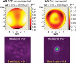
Laser scientists generally introduce an adaptive-optics system between the laser-amplification chain and the focusing optics to compensate for the optical aberrations introduced during amplification. The focused spot thus takes on an almost perfect shape and the optical power density on the target improves significantly (see Fig. 1).
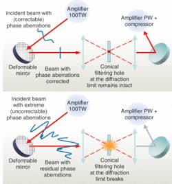
Although this arrangement is effective for focusing the laser beam on the target, another possible architecture can optimize amplification even further. The concept—“adaptive optics inside,” (AOI)—involves placing the deformable mirror between any two steps within the laser amplification chain (see Fig. 2).In this configuration, the adaptive-optics system not only improves the spot focusing, but also reduces the risk of internal damage to the laser system from local overintensity of the laser caused by beam heterogeneities or from local wavefront defects (optical aberrations) in the propagating beam. The AOI approach limits the risk of this type of damage and protects the internal components, while optimizing the laser output. The approach acts on two levels: the aberration corrections in the middle of the laser-amplification chain reduce the amplitude of the aberrations that propagate as well as the distance that higher-amplitude aberrations travel.
The optical fuse
Lasers are becoming increasingly powerful, and their technical feasibility is proved by recent installations of high-intensity lasers such as ILE (www.ile.osaka-u.ac.jp/index_e.html), ELI (www.extreme-light-infrastructure.eu/), PETAL (petal.aquitaine.fr/), HiPER (www.hiper-laser.org/), and lasers at the Nevada Terawatt Facility (www.ntf.unr.edu/) and DARPA’s SHEDS program (www.darpa.mil/mto/programs/sheds/). With this power comes the need to protect sensitive components in the laser-amplification chain such as the crystals and compressor networks that are precious and difficult to replace. To this end Imagine Optic teamed with Amplitude Technologies (Evry, France) to develop an adaptive-optics application called the optical fuse (see Fig. 3). We filed a patent for this application in 2007.Flat metallic filter holes are currently used during amplification in some lasers to improve beam quality by eliminating the majority of aberrations present. Unfortunately, this approach has important limitations in the domain of high-power lasers. To function, the filtering hole must be exceptionally small, approximately equal to the size of the beam’s diffraction limit. The low damage threshold of the materials used to manufacture these simple filters causes them to collapse and they melt in the presence of high-intensity laser beams. Furthermore, this simple approach is not capable of managing the wide ranging high- and low-spatial-frequency aberrations that accumulate in these beams during amplification.
The optical fuse overcomes the limitations of its simpler cousin by associating an adaptive-optics phase-correction mechanism with a conically shaped filtering hole made of a dielectric material with a very high damage threshold. The optical fuse is deployed in a manner similar to that of simple hole filters and can be placed at the exit point of any step in the amplification chain. In operation, the phase-correction technology compensates for low-spatial-frequency aberrations and focusing errors so that almost all of the laser-beam energy passes through the filtering hole. Then the conical filter prevents high-spatial-frequency aberrations that can’t be corrected by adaptive optics through the chain. The efficiency of the filter is inversely related to the size of the filter hole, so a major benefit of using adaptive optics here is that it enables the use of a filter hole whose diameter is close to the diffraction limit of the beam.
The optical fuse comes into its own in two different cases. First, when a problem during amplification causes beam aberrations to exceed the correction ability of the adaptive-optics system; and second, when, for whatever reason and after multiple firings, the wavefront of the beam suddenly and unexpectedly changes. In these cases, the size of the focal spot exceeds that of the filter hole’s focal plane. When this happens either the focal spot is so large that only a fraction of the energy passes through the aperture, or the energy in the focal plane is so great that it causes the filter to collapse. In both cases, potentially damaging energy is stopped from passing on in the amplification chain. The conical form of the filter hole and the inherent properties of its dielectric material form an ideal filter that enables the fuse element to be extraordinarily robustit only collapses when the energy interacting with its surface exceeds dangerous levels.
Depending on the target composition and geometry, this approach can also prevent feedback from re-entering the amplification chain. Here, the filter protects optical elements situated in front of it (that is, those situated between the laser output and the filter hole) as well as those behind it.
Although the fuse element—the filter hole—must then be changed after a collapse, the fragile and expensive optical elements in the cavity are protected. The fuse element itself is disposable and easily replaced at a small cost compared to the optical elements it protects.
XAVIER LEVECQ is chief research officer at Imagine Optic, 18 rue Charles de Gaulle 91400 Orsay, France; e-mail: [email protected]; www.imagine-optic.com.


