Quantum optical coherence tomography (OCT) has, for the first time, been shown to be a viable biological imaging technique, says M. Boshra Nasr, a postdoctoral researcher in the Quantum Imaging Laboratory at Boston University (Boston, MA). Nasr led a project that has produced the first experimental quantum OCT (QOCT) images of a biological sample.
Quantum OCT holds strong appeal because, unlike classical OCT, it is inherently immune to group-velocity dispersion (GVD), which degrades axial resolution.1 This immunity is a direct result of the frequency entanglement inherent in the light source used in such a scheme; QOCT is a fourth-order interferometric optical-sectioning scheme that makes use of frequency-entangled photon pairs that are generated via the process of spontaneous optical parametric downconversion.2 By contrast, conventional optical coherence tomography is a second-order interferometric scheme that enables high-resolution axial sectioning through the use of ultrabroadband light–but that’s what leads to GVD.
In addition to being immune to GVD, QOCT is able to deliver double the resolution for the same bandwidth. Quantum OCT had previously been shown to work on other materials, “but it’s harder to work with biological specimens,” Nasr says.3
The setup
The researchers’ experimental setup is a modified Hong-Ou-Mandel interferometer in which a biological sample is placed in one arm, and a delay in the other. A monochromatic krypton-ion laser, operated at a wavelength of 406 nm, pumps an 8-mm-thick type-I lithium iodate nonlinear crystal. A fraction of the pump photons transform into pairs of down-converted entangled photons (biphotons). The entangled photons, with a wavelength of 812 nm, have horizontal polarization with respect to the optical table and are emitted in a noncollinear configuration into two beams.
The photon in beam 1 is directed to the delay arm, where it is transmitted through a polarizing beamsplitter (PBS) followed by a broadband quarter-wave plate (QWP), which converts it into a circularly polarized photon. An achromatic lens then focuses the beam onto a mirror. The lens-mirror combination is scanned in the z direction during the experiment. The reflected photon becomes vertically polarized after traversing the QWP for a second time, and it then reflects from the PBS.
The photon in beam 2 is directed to the sample arm, which contains an identical set of optical components as the delay arm, except that the mirror is replaced by a biological sample that can be scanned in the transverse plane (x and y directions). The photons returned from the delay and sample arms are each directed to one of the input ports of a nonpolarizing beamsplitter (NPBS). Beams 3 and 4, at the output of the NPBS, are directed to single-photon-counting detectors after passing through long-pass filters with a cutoff wavelength of 625 nm. A coincidence circuit measures the coincidence rate between the detectors within a 3.5 ns time window.
Sweeping the delay arm’s lens-mirror combination in the z direction and recording the coincidence rate with the sample fixed at a particular transverse position produces a single QOCT depth scan. Collecting all scans for different transverse positions provides the 3-D optical sections for the sample.
Initial results, future plans
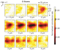
The researchers chose for their sample white-onion-skin tissue, which they coated with spherical gold nanoparticles to increase its reflectance. The gold nanoparticles were functionalized with bovine serum albumin. Their results were presented in transverse sections at different depths (see figure). The x-y sections, 75 × 100 µm2 each, were taken at depth intervals of 1 µm. The z origin was chosen to approximately coincide with the surface of the onion-skin cells so that, roughly speaking, negative z positions correspond to sectioning in the air above the sample, while positive z positions correspond to sectioning within the cells. A strong QOCT signal is indicated by a decrease in the observed coincidence rate, corresponding to a path-length match between the delay and the sample arms. The C-scan at z = 2 µm clearly shows the elongated structure that is characteristic of onion-skin cells.
Now the researchers at the Quantum Imaging Laboratory, including Dr. Nasr, are looking to make the process more practical; the current arrangement required tens of hours to image. Achieving greater practicality will require more sophisticated components, he says, so they will seek to work with groups that produce superconducting single-photon detectors, for instance. Such detectors, and faster coincidence circuits, should increase speed by a couple orders of magnitude and boost the signal-to-noise ratio, he explains. Similarly, biphoton sources with ultrahigh axial resolution promise to further improve QOCT. His ultimate goal is to see the technique transformed into a clinical tool. While the results are inspiring, “we are still at the very beginning,” he says.
REFERENCES
- M.B. Nasr et al., Optics Express 12, 1353 (2004).
- A.M. Steinberg et al., Phys. Rev. Lett. 68, 2421 (1992).
- M.B. Nasr et al., Phys. Rev. Lett. 91, 083601 (2003).

