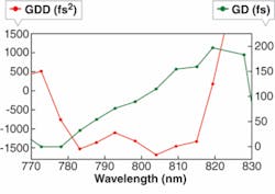
An improved chirped-mirror design developed by scientists in the Krausz group at Ludwig-Maximilians-Universität-München and the Max-Planck-Institut für Quantenoptik (both in Garching, Germany) has a high-enough group-delay dispersion that it can be used for purposes traditionally reserved for prisms or gratings, such as chirped-pulse amplifiers (CPAs) or high-energy femtosecond-laser chirped-pulse oscillators (CPOs).1
Ultrafast-laser systems often require optics that provide a time delay that varies depending on the wavelength of the light striking them—a property called group-delay dispersion (GDD). Such optics, which can take the form of prisms, gratings, or chirped mirrors, can be used to compress or stretch femtosecond pulses. While chirped mirrors are the simplest of these optics, they usually provide only very small amounts of GDD, making them of only limited use.
The low-loss high-dispersion mirror (HDM) was fabricated in two prototype versions: one for the 780 to 820 nm spectral range (Ti:sapphire), with 85 layers and a GDD of about ~1300 fs2 at 800 nm; and one for the 1020 to 1040 nm range (Yb:YAG), with 65 layers and a GDD of about ~2500 fs2 at 1030 nm.
The dielectric layers are alternating layers of tantalum pentoxide (Ta2O5, with a refractive index of 2.12 at 800 nm) and silicon dioxide (SiO2, with an index of 1.47 at 800 nm). They were produced by means of magnetron sputtering, determined to be the deposition method with the highest accuracy and thus the best way to keep manufacturing errors under control.
Use with a CPO
The reflectivity of both the 800 and the 1030 nm coatings was measured to be about 99.9%, which the researchers say makes them practical for stretching or compressing ultrafast pulses by a factor of at least a thousand while losing no more than 10% of the pulse energies to mirror absorption or scattering.
The 800 nm HDMs were designed to compress the pulses delivered by a Ti:sapphire CPO (see figure). Because the amount of GDD required for this purpose is about ~25,000 fs2, the ultrafast beam had to be bounced off the HDMs 20 times. Even so, the researchers determined (via computer simulation) that after 20 bounces a 60 fs pulse retained its incident duration and greater than 95% of its input energy within the main pulse, despite the presence of spectral ripples in the mirror’s GDD plot.
The Ti:sapphire CPO produced chirped pulses with a 2 ps duration, a 250 nJ energy, and a 5 MHz repetition rate. Prior to use with the new HDMs, the CPO was used with a two-pass prism compressor, which compressed the pulses to their bandwidth-limited duration of 65 fs, but with an energy throughput of only about 50%. When the prism compressor was replaced with the HDMs in a 20-bounce arrangement, the energy throughput efficiency jumped to 98%, while the compressed pulse duration remained at 65 fs.
Next: use in a CPA
“Our dispersive mirrors work successfully with millijoule-level, sub-30-fs pulses for a full beam (without focusing),” says researcher Vladimir Pervak. “The main goal in developing the HDMs was to provide high-enough intracavity dispersion for high-energy Ti:sapphire and Yb:YAG oscillators. When the mirrors were successfully realized and tested, we found that we can reach our next goal: to replace prisms and gratings in existing CPA compressors.”
In a CPA, which amplifies femtosecond pulses to millijoule levels, the pulses are first stretched and then amplified by a factor of a thousand and million, respectively, in an amplifier, explains Pervak. Pulse stretching is necessary to prevent damage of the active medium of the amplifier due to high intensities.
“To make the amplified pulses short once more and ready for nonlinear experiments or technological processes sensitive to the pulse duration, one has to then use a compressor,” says Pervak. “The drawbacks of existing compressors are first, a large size, bringing undesirable beam pointing errors at the target, and second, relatively long pulses. The first is a result of a large compression factor (almost 103, from 5 ps to 20 fs): the length of the compressor is proportional to this factor. The second is a result of noncompensated high-order dispersion (leading to an insufficient compression factor)—an intrinsic problem of all current compressors.”
High-dispersion mirrors, however, can be designed to compensate for up to fifth-order dispersion. In addition, their high amount of dispersion per reflection allows them to be energy efficient. Pervak sites an example of the latter: for the required compensation of 2 × 10⁴ fs2, a standard chirped mirror—with GDD of ~50 to ~100 fs2 and a reflectivity of 0.995—would require 200 reflections, leading to a throughput of only 37%, versus on the order of 90% for the HDM. Even more important, an ordinary chirped mirror would destroy the pulses because of errors in the mirror’s GDD curve, while the HDM does not.
“The size of the compressor (in the case of the HDM) will be tens of centimeters instead of many meters, thus drastically reducing the beam-pointing errors,” adds Pervak.
REFERENCE
1. V. Pervak, et al., Optics Express 16(14) 10220 (July 7, 2008).

