CRAIG HANSON
Multiphoton excitation was first theorized in 1931 by Maria Göppert-Mayer in her doctoral dissertation during the early development years of quantum mechanics.1 Yet, it was not observed experimentally until 30 years later–shortly after the invention of the laser–and it has taken another 30 to 40 years for it to revolutionize biomedical imaging as the basis for multiphoton laser scanning microscopy, commonly referred to as MPM.
Today, MPM is the leading noninvasive laboratory tool offering high-resolution, three-dimensional imaging of thick tissues, intact tissues, and even live specimens, in vivo, without inflicting damage to the specimen. It has been used to observe subcellular events and is now being applied to all major areas of biological research, from studying stem cells, cancer, and processes of functioning neurons.
Due to their high peak powers, turnkey diode-pumped femtosecond Ti:sapphire laser systems have made MPM more feasible. With the large investment in instrumentation (MPM systems including the Ti:sapphire laser and confocal microscope can cost upward of $500,000 to $1 million), the importance of inexpensive, quality optics cannot be overlooked. High-quality mirrors and filters can greatly affect the performance of MPM instruments, improving signal-to-noise ratio and imaging quality.
Two-photon excitation microscopy
While MPM encompasses any imaging microscopy where the signal is generated by a multiphoton process (such as second- and third-harmonic generation, coherent anti-Stokes Raman scattering, and three-photon excitation), two-photon fluorescence is typically the primary method.
In the nonlinear two-photon excitation (TPE) process, two lower-energy (longer wavelength) photons excite the fluorophore to the higher energy state. As the fluorophore relaxes, it emits, or fluoresces, a photon of lower energy than the combined two-photon energy. Quantum mechanically, a single photon is absorbed exciting the fluorophore to a virtual intermediate state whose lifetime is about 1 × 10-18 s or an attosecond. There, a second photon is absorbed and the fluorophore is brought to a final higher energy state with the resulting fluorescence emission proportional to the square of the excitation intensity. Fluorescence can be generated at other wavelengths including the green; the only requirement is that the combined two-photon energy is greater than that of the fluorescent photon.
Because TPE is a two-photon event, the probability that two photons are absorbed almost simultaneously is very low. Higher photon densities increase the probability of TPE, making it much more likely to happen at the focal point of a tightly focused beam than at any other point. There is minimal “out-of-focus” signal as in single-photon fluorescence microscopy—giving two-photon microscopy (TPM) automatic sectioning capability without having to use any pinholes as required in confocal scanning microscopy. Since the incident laser radiation of TPM is at a longer wavelength, other advantages over confocal microscopy include reduced photobleaching and phototoxicity, reduced scattering effects, and deeper penetration depths–hundreds of microns versus only tens of microns for confocal microscopy.
Despite these advantages, TPM was initially considered impractical as the high powers required for TPE would have damaged the sample. However, in 1990 Denk, Strickler, and Webb used a femtosecond dye laser in the first successful demonstration of TPM.2 The combination of ultrashort pulses and low duty cycle (100 fs full-width half-maximum at 80 MHz repetition rates) for these ultrafast lasers offered high peak powers with low average power–the ideal combination to eliminate thermal damage issues. But because these lasers were cumbersome, messy, and required multiple mirror sets and adjustments, it wasn’t until the recent advent of turnkey, hands-free, commercially available, diode-pumped Ti:sapphire lasers that MPM became practical.
Optics and the TPM system
A typical TPM system consists of the excitation diode-pumped Ti:sapphire laser; scanning and imaging optics for creating the 2-D or 3-D image; photomultiplier tubes for detecting the fluorescence emission; lenses for focusing the excitation onto the sample and for collecting the fluorescence signal; and mirrors and filters (see Fig. 1).
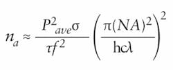
When selecting the beam-steering mirrors, the dispersive characteristics of the mirror must be considered. Because the number of photons absorbed per fluorophore per pulse, na, is given by:where Pave is the average incident optical power, σ is the fluorophore’s two-photon absorption cross section at wavelength λ, τ is the pulse duration, f is the laser’s repetition rate, NA is the numerical aperture of the focusing objective, h is Planck’s constant, and c is the speed of light, it is imperative to maintain the shortest pulse durations and highest powers. Ultrashort pulses have a wide frequency bandwidth or wavelength spectrum, and therefore, the dispersion in mirrors, filters, lenses, and attenuators can broaden the Ti:sapphire femtosecond pulse, significantly decreasing the fluorescent signal.
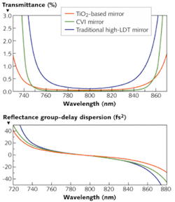
The most suitable optics will have minimal group-velocity dispersion (GVD) over the spectral range of the Ti:sapphire pulse. In a dispersive medium, different frequency components of the pulse travel at different velocities. A material with normal dispersion has a refractive index that decreases with increasing wavelength; the longer red components travel faster than the shorter blue components and the pulse is said to be positively chirped. Negative chirp occurs in anomalous dispersive materials; here, the red components are retarded with respect to the blue components. In either case, the pulse is stretched out in time, lowering the peak power. With zero-GVD optics, the pulse will experience little to no dispersion and no decrease in the peak power.
Almost all materials, however, exhibit normal dispersion, including the imaging system before the sample. Even with near-zero GVD mirrors, the pulse will experience some pulse spreading before reaching the sample. Dispersion-compensation mirrors that correct for phase distortions can optimize the pulse at the sample. Mirrors that have a higher group delay for longer wavelengths (negatively chirped or negative GVD) can compensate for the normal dispersion of the microscope itself.
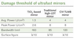
Another consideration when choosing optics is the laser damage threshold (LDT) as measured in J/cm2 for pulsed applications. The high peak powers of ultrafast laser pulses can easily cause damage to coatings by attacking the electronic bonds of the dielectric material itself. For MPM and TPM, the mirrors must have low GVD and high LDTs. Traditional high-LDT mirrors–made from combinations such as silicon or zirconium dioxide (SiO2 or ZrO2) or mixtures including hafnium or aluminum–do not have a high enough reflectivity over the entire Ti:sapphire bandwidth. Broader reflectivity bandwidths can be achieved by using different coating materials, such as a SiO2/TiO2 combination. However, that reduces the LDT due to the slight absorption of TiO2.On the signal side, the optics such as the dichroic beamsplitter and emission filters can affect the signal-to-noise ratio and clarity of the image. The optics are critical because even a small amount of excitation light can override the small fluorescent signal at the sensitive photomultiplier tube. The filters must block the excitation light fully and over the broad spectrum of the Ti:sapphire laser while transmitting the weak emitted fluorescence.
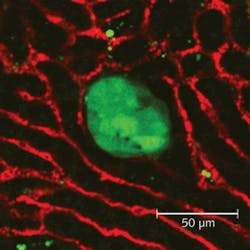
Until recently, optical filters couldn’t achieve both the ultrahigh transmission in the passbands and the steep transitions required for maximum out-of-band rejection. Today modern filters are manufactured using hard coatings that offer better environmental stability and durability. With hard coatings, more layers can be deposited and hard-coating filters can achieve better transmission in the passband, along with deeper blocking over a wide spectrum, resulting in improved TPM signal quality.Such improvements allowed researchers at Vanderbilt University to utilize MPE imaging to examine metastatic events from breast-cancer tumors to the liver, and to determine the timeframe in which metastatic cells extravasate from the vasculature to establish a new tumor in the liver. The researchers developed a technique for examining ex vivo liver explants in an experimental model of breast cancer metastasis to the liver. In this model, mammary tumor cells expressing green fluorescent protein are injected into the spleen of mice (see Fig. 3).
REFERENCES
- M. Göppert-Mayer, Ann. Phys. 9, p. 273 (1931).
- W. Denk et al., Science 248, p. 73 (1990).
- M. D. Martin et al., Clin. Exp. Metastasis 25, p. 877 (2008).
Craig Hanson is a product manager at CVI Melles Griot, 200 Dorado Place SE, Albuquerque, NM 87123; e-mail: [email protected]; www.cvimellesgriot.com.


