Typical silicon (Si) solar cells appear bluish for a reason. Because of the high refractive index of Si, the material’s bare untreated surface reflects 30% or more of the light it receives; thus, most Si solar cells are coated with a single-layer quarter-wave antireflection coating that usually works better in red than blue, creating the color (and still reflecting up to 20% of the usable light).
Many researchers are hard at work trying to find a better alternative—one that not only reflects a lot less, but does so for a broad range of wavelengths and incidence angles. Graded-index (GRIN) coatings consisting of several layers, each with a different refractive index, are a popular choice, but the coatings arrived at in previous designs have not performed optimally or have been quite complicated.
To create simpler GRIN solar-cell coatings that transmit well under real-life conditions, researchers at Rensselaer Polytechnic Institute (RPI; Troy, NY) have developed a “genetic” coating-design algorithm that, by iteratively generating many designs, rejecting the worst, and “mutating” the rest, naturally arrives at a top-quality design.1 The algorithm does this straightforwardly even if many application-specific parameters are used for the basis of the optimization.
Three layers
For the three-layer experimental coating design, the researchers chose titanium dioxide (TiO2) as the inner layer because TiO2 has a high refractive index (2.37) and high transparency. The coating for the outer layer was porous SiO2 with an index of 1.05 (90% porosity). The middle layer was also porous SiO2, with its index optimized by the program. The program was set to optimize for average reflectance weighted equally over a wavelength range of 400 to 700 nm and incidence angles of 0° to 90°, for an average of the TE and TM polarizations.
The calculated refractive index of the coating’s middle layer turned out to be 1.35, or a 24% porosity. The calculated average reflectance over all angles and wavelengths for the three-layer GRIN coating was 5.1%—far better than the calculated average reflectance for a single-layer coating (17.0%), a zinc sulfide/magnesium fluoride bilayer coating (10.8%), and a continuous quintic GRIN coating (17.6%).
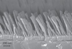
The RPI researchers fabricated their three-layer GRIN coating (see figure) and measured the index of each layer using ellipsometry; the only variation from the calculated values was the middle layer, which had an experimental index of 1.40. They also created a standard single-layer quarter-wave silicon nitride coating for comparison.
At normal incidence and averaged over 400 to 700 nm, the measured reflectance for the three-layer GRIN coating was a mere 3.9%. Averaged over a 40° to 80° angle and wavelengths of 400 to 700 nm, the three-layer coating showed a reflectance of 6.1%, compared to 22.4% for the standard single-layer coating. Birefringence (the difference in reflectance between TE and TM polarizations) for the experimental GRIN coating was only 0.5%.
Outdoor use
As for the outdoor durability needed for practical use on solar cells without a covering, the coating needs further development. “Due to the high porosity, and hence less mechanical stability than ‘dense’ coatings, there would be a difficulty in using this antireflection coating for practical applications as it is,” says Jong Kyu, one of the researchers. “It would have to be covered by glass for durability and weatherproofing.” (The use of glass is a workable option, as glass has a reflectance far lower than Si and can be easily coated for even lower reflectance.)
The group is working on other options, too. “We are developing a ‘pore-closing’ technique in which the low-refractive-index layer is covered by a thin layer, so that the entire coating is robust and durable enough to handle outdoor weather,” notes Kyu. “One alternative way to make a low-refractive-index layer is spin-on sol-gel technology, which is robust and durable. Please note that the low-refractive-index layer in the publication is a kind of extreme case, which is a very porous layer with a refractive index less than 1.1. Using our genetic-algorithm optimization, we can design and fabricate a multilayer antireflection-coating structure with a low-refractive-index layer (an index on the order of 1.2) that is robust to get similar results—broadband, omnidirectional, and low reflectivity”.
REFERENCES
- D.J. Poxson et al., Optics Lett. 34(5) p. 728, March 15, 2009.

