Most optical systems used in lithography include both illumination and imaging parts. The illumination part projects the light source into the plane of the objects of the optical system. In most cases, illuminators use the Kohler type of illumination, when the light source is projected to infinity. But in some cases, it is necessary to use the “critical” type of illumination when the light source is projected directly into the plane of the objects of the optical system. This makes it possible to control the plane of objects, and to change the configuration of the object without changing the reticle. The object must include a set of spatial light modulators (SLMs) that form the desired configuration, which are then transferred to the image plane.
By managing the SLM set, you can change the configuration of the object and exclude its replacement. That means that one reticle can be used to obtain different images. In this case, the SLM kit makes it possible to eliminate the replacement of the reticle when changing the geometric configuration of the object, which is achieved by changing the transmission (reflection) of the light flux.
Using a universal optical component that does not require replacement to obtain various images in the wafer plane makes it possible to speed up the printing process and to also reduce the cost of chip production technology. The main topic of this article is to describe an illumination multichannel optical system that allows finding an acceptable result.
For this purpose, each channel of an optical system forms a relay that creates a real image. Each channel of such an optical system must consist of at least two optical components to obtain a valid SLM image in the reticle plane. In this way, several independent SLM images are simultaneously formed within the reticle plane, which simulates the required circuit. Within the image plane, images are transformed by switching off or on a single channel or their group. As a result, there is no need to replace reticles when printing various schemes.
A multichannel relay optical schematic
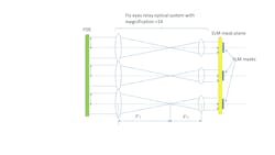
The simplest optical design of a fly-eyes relay consists of two optical lens components: front and rear. The front optical components create a telecentric beam (for the aperture rays) and the rear components create an image (focusing this beam on the reticle).
Since the optical system is multichannel, the reticle depicts a complete SLM picture of objects located within the object plane. When the brightness of the light flux passing through the individual SLM on the reticle changes, the illumination of the light spot changes (that is, the brightness of the image changes). This means objects of various configurations and brightness can be obtained on the reticle.
A complete image of the object is created on the reticle—it consists of images of individual channels. By changing the brightness of individual SLMs, different configurations of the microchip can be achieved without changing the reticle. The general optical schematic of the fly-eyes relay is shown in Figure 1.1, 2
FDE is the field-defining element, and F’1, and F’2 are the focal lens of fly-eyes relay optical components. The linear magnification Γ of such an optical system is calculated by the following formulas:
Γ=(n2 F’2)/(n1F’1); or
Γ=(n2 sinα)/(n1 sinα’);
where n1 and n2 are indexes of refractions in the first and second relay lenses, respectively.
F’1 and F’2 are the fly-eyes relay optical elements’ focal lengths and α; α’ are numerical apertures in the object and image spaces. Depending on the focal ratio of the relay lenses, both an enlarged and/or reduced SLM image on the reticle can be achieved.
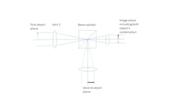
One way to expand the working capabilities of the relay optical system is to include the second channel in the relay optical scheme. This will allow the simultaneous depiction of two planes of objects on one reticle, which results in a combined image of the two objects. To achieve this, it is necessary to include the beamsplitter and one additional lens in the relay optical scheme.When using a two-channel optical relay (see Fig. 2), the following possibilities appear:
1. Each channel can build an image of an object on a reticle with a different magnification (the focal lengths of the frontal optical components must be different).
2. The numerical aperture (NA) in the channels can have different values.
3. In the image plane, it becomes possible to obtain various complex (composite) configurations of objects.
If the first optical relay channel within the object plane (FDE) is located, then it’s necessary to place a fiber or bundle in the second channel within the plane of objects to create an alternative object. The second channel can be used to correct the image quality from the first channel. It also changes the structure and shape of the light spot, which allows for expanding the light capabilities when obtaining complex images.
The presence of two lighting channels allows you to find the best geometric shape for the light spot. And two light spots overlapping each other enables you to construct an interference pattern, which expands the scope of this lighting method.
Practical relay system implementation
The geometric dimensions of SLM are several microns, so the relay must create light spots within the image plane of the corresponding area. Therefore, the linear magnification Γ of the relay must be less than 1X. This is necessary to create a light spot whose diameter corresponds to the size of the SLM. In some cases where small-size SLMs are used, two or three relays system are necessary, each with magnification less than 1X. The magnification of such an optical system (Γ) is determined by the following formula:3, 4
Γ= Γ1 Γ2.. Γn,
where Γ1…Γn are magnifications of separate relays included in the optical system. To obtain the required size of the image (light spot) of a cell on the SLM, it is necessary to determine the magnitude of the linear magnification, which depends on the ratio of the focal lengths of the relay lenses or the ratio of NA at the input and output of the relay optical system.
It should also be noted that when designing an optical system of several relays, the rule must be observed that the numerical aperture of the subsequent optical system should be greater than or equal to the numerical aperture of the previous optical system. That is NA i+1>NAi, where i is a number of the relay system.
Critical type of illumination
A multichannel optical illumination system that implements the “critical type of illumination” can be adopted by the semiconductor industry. This type of lighting system eliminates replacing the reticle while printing microchips. And it’s more economical because it eliminates the need to manufacture numerous reticles, which greatly simplifies and speeds up the process of printing microcircuits.
The SLM can be reconfigured, in which the image of the microcircuit is projected onto the reticle—so that different images can be sequentially obtained on one reticle and printed. This method also enables “resolving” the image’s smallest details.
REFERENCES
1. Y. Vladimirsky and L Ryzhikov, U.S. Patent 7532403 (2009).
2. L. Ryzhikov and Y. Vladimirsky, U.S. Patent 7859751 (2010).
3. B. Begunov, Geometrical Optics, 152 (1966).
4. G. H. Seward, Optical Design of Microscopes, SPIE Press (2010).

