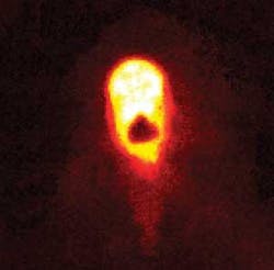
Keyhole welding, one of the most common means of laser welding in industry, has gotten a quality-control boost in the form of a new image-processing method developed by researchers at the Fraunhofer Institute for Physical Measurement Techniques (Freiburg, Germany). The team has demonstrated a feedback system for high-speed imaging of the process that can monitor the welds and adjust the incident laser power with a response time of just 70 ms.1
As the incident laser strikes the first sheet to be welded, melting it, vapor and liquid melt are produced. For a structurally sound seam, the beam must just penetrate the last, bottom sheet, making a temporary “keyhole.” As the laser is scanned, the melt flows backward, closing the keyhole behind it and leaving a secure weld. However, the process is exquisitely sensitive to the input laser power. Too little, and the bottom sheet does not provide a sufficient amount of the melt; too much, and the beam simply cuts through the sheets.
The established method of ensuring that a stack of sheet metal is welded together is by imaging the process coaxially, either by way of a coaxial reflection of the working laser or on the reverse of the workpiece. However, the image processing that ensures a precise, controlled laser power has not kept pace with the speed of the welding itself, says Andreas Blug, the Fraunhofer researcher who led the team that developed the new technology.
“You have a camera and say that if in a certain percentage of images, this hole appears, then it’s OK,” he says. “It’s a monitoring system without feedback.”
That means that a significant period of time can pass before an inappropriate laser power is caught—a significant problem in the automotive industry where the process is most commonly used.
“There have been attempts at implementing feedback, but the problem was the computing power,” he said. “The hole is moving rapidly—between 5000 and 10,000 images per second. You can’t acquire slower than that, otherwise the contrast goes down.”
Processing at the pixel level
Now the Fraunhofer team has implemented a so-called “cellular neural network” camera, image processing, and feedback loop that allows real-time imaging with frame rates up to 14 kHz. The eye of the system is an Eye-RIS camera developed last year and just recently commercially available from AnaFocus (Seville, Spain CK). The camera incorporates 25,000 pixels, each with its own microprocessor built in. The “cellular” aspect means that part of the image processing happens at the pixel level, as each pixel can share signal information with its neighbors—leading to local images that comprise a whole. The image is processed in parallel, by all 25,000 pixels, rather than the usual serial download of each pixel’s information across rows into one or a few processors.
“State-of-the-art feedback systems need about a millisecond to evaluate these images, which is too slow,” Blug says. He notes that the new system’s 70 ms response time is faster than needed, but it is efficient.
Though the idea of cellular-neural networks has been around for two decades, it has only recently been put into practice. The computing circuitry underpinning the neural network has been developed in the last five years, but it is the implementation with high-performance optical systems that is making the approach useful for industrial applications. Fraunhofer’s key work in developing the approach was to translate the hardware into a full image-based feedback system.
“You have to redevelop the algorithms in the processing to make good use of this parallel computing,” Blug explains. “It’s a different way of thinking, with local images from neighboring pixels.”
The team’s prototype feedback system is designed to complement rather than replace existing monitoring systems, and the team is currently in negotiations with several industrial firms. “We are looking at applications with laser materials processing like ablation or cutting, because they have high dynamics; you can look in between the pulses, and that’s what we’re trying now. We want to get it into production.”
REFERENCE
- Nicolosi et al., IEEE Internatiaonal Joint Conf. on Neural Networks, IJCNN (June 14-19, 2009)
