Motion Control: Galvanometer-assisted stent processing increases next-generation device throughput
SCOTT SCHMIDT and DAVID GILLEN
Cylindrical laser micromachining has been a standard means of stent production for some time. The typical motion control solution applied for this application uses two servo-controlled stages-namely, a rotary axis carried by a linear axis-positioned beneath a fixed laser beam delivered through a co-axial gas assist nozzle (see an example at https://youtu.be/_8Nox7XHvow).
The specific stage choices have changed over the past years, beginning with belt- or screw-driven linear and worm-and-wheel rotary stages, and eventually converging on direct-drive technology for both axes. While this evolution has offered substantial process time and part accuracy improvements, the basic architecture itself may be approaching its fundamental limit for optimization.
An analysis of current cylindrical laser micromachining systems yields a few conclusions:
1. Two established figures of merit for the performance of such systems are cycle time to produce a single part, and overall form error of the final part. Furthermore, a comparative curve of cycle time vs. form error is a natural figure of merit to develop for any given stent-cutting system (see Fig. 1);
2. Achievable acceleration values are constrained by the moving mass-to-motor force ratio of the linear stage, and (similarly) the rotating inertia-to-motor torque ratio of the rotary stage;
3. All dynamic errors induced in the part arise from changes in axis velocity (i.e., acceleration and deceleration)—at constant (or zero) velocity, no dynamic errors occur; and
4. Combining conclusions (2) and (3), we may ascertain that as mass-to-force or inertia-to-torque ratios degrade, part throughput and/or cycle times will suffer.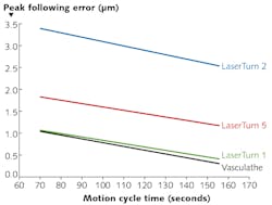
Interventional cardiac and neural device technology has progressed toward smaller diameter stents, which worsens the cycle time-vs.-form-error plot conclusion (1) above. Smaller stents infer a less favorable inertia-to-torque ratio, as the workpiece holder (typically a precision collet) becomes substantially more significant compared to the inherent inertia of the (presumably smaller) rotary stage. Furthermore, these smaller diameters have resulting smaller circumferences and therefore more rapid acceleration required by the rotary stage to maintain the same surface speed on the part as seen by the laser. As detailed above, higher acceleration equates to larger errors.
There are a number of new challenges facing the manufacturers of interventional medical devices, and these can be summarized by three headings:
1. Faster throughput required for existing and smaller diameter stents;
2. Novel materials being introduced; and
3. Laser sources changing.
Faster throughput
When a new medical device is being brought to market, manufacturing costs are not the primary driver and budgets will be allocated to ensure the device is brought to market, investor expectations are met, and share prices are maintained. However, as a device matures, manufacturers will seek to improve efficiency by reducing manufacturing costs.
Key to reducing costs is increasing the throughput of the production system, ensuring capital expenditure is kept to a minimum. However, this improvement in throughput cannot be at the expense of accuracy.
Novel materials
Bare metal stents (BMS) based on stainless steel were introduced as a means of providing mechanical support and preventing artery walls from closing up after balloon angioplasty. Stainless steel was substituted with biocompatible memory-based alloys such as Nitinol, which improved stent delivery and expansion within the artery.
Although bio-compatible, BMS could lead to thrombosis and inflammation, and medical device companies looked to novel methods to prevent these secondary complications. One method is to coat the BMS with a degradable polymer, which releases drugs that inhibit tissue growth over time and prevent the re-narrowing of arteries. These are known as drug-eluting stents (DES), and have overtaken BMS as the stent of choice.
A third route is to remove the metal component altogether and make stents from bioabsorbable materials. These bioabsorbable stents can be made from materials such as magnesium, zinc, and polylactic acid, and require non-standard laser cutting techniques to ensure low-heat-input, high-tolerance manufacture.
New laser sources
Initially, BMS were cut with YAG-based laser systems, which were suitable for stainless steel. The introduction of Nitinol coincided with the increased use of fiber-based laser cutting systems. Fiber lasers could be pulsed at up to 60 kHz, giving a finer control of heat input. This allowed stent strut width to be decreased even further, with sub-100 μm becoming industry norms.
In general, stents must go through a series of post-processing steps to ensure that the material is passivated and all rough edges are removed. These post-processing steps reduce production line throughput and increase manufacturing costs.
Ultrashort-pulse (ultrafast) lasers are a successful new tool for stent production for two reasons. First, ultrashort-pulse lasers have a lower heat impact on the material and can reduce surface debris buildup, which was a major marketing tool for their introduction. That said, there is a lack of evidence that the use of ultrashort-pulse lasers reduces post-processing costs. Edges still need to be smoothed through electro-polishing and, given the high cost of ultrashort-pulse lasers, a stronger economic argument needs to made for their widespread acceptance.
Second, and more importantly, ultrashort-pulse lasers tend to be material-independent and it is now possible to machine almost any medical device material with a sub-10 ps laser source. This is important when looking to machine materials such as polylactic acid, where absorption at 1 μm is non-existent.
One important characteristic of ultrashort-pulse lasers that has not been fully utilized in stent manufacturing is the high repetition rates (up to 500 kHz). This high pulse rate allows the laser to be moved at high speed, measured in meters per second, relative to the stent while still maintaining a sufficient pulse overlap. Traditional stent manufacturing with linear stages is limited by the system dynamics and cannot reach these high speeds, thereby limiting one of the main benefits of an ultrashort-pulse laser.
Considering the demands of advancing technology in stent production, achieving the required increase in overall system dynamics while maintaining part accuracy seems impossible with traditional linear and rotary axes. So, what can be done?
Advancing stent production technology
One potential solution may be a new rotary stage design. As workpieces become smaller (or even stay the same size, but require multiple processing passes), the rotary axis is typically the limiting factor when compared to the linear stage. We might attempt to devise a smaller rotary stage with reduced inertia, or perhaps invent a workpiece-holding strategy different from the precision collet mechanisms currently in use. However, smaller holders will not be as stiff and will have smaller closing surfaces, imparting greater axial and radial errors during clamping and processing. Solving these problems simultaneously seems unlikely in the near future.
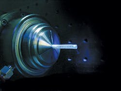
Another solution is to devise a fundamentally different strategy for delivering the laser to the part. Instead of using a static tool (the laser spot) and moving the workpiece, why not instead offload some of the required high-speed motion to the tool? In other words, we should consider the use of a high-speed galvanometer system mounted overhead of the workpiece, and move the laser instead of moving the part (see image at the top of this page).
A linear and rotary stage will still be required (the rotary as defined in the scenarios below, and the linear to enable part advance and cutoff), but their required dynamics will be much less, essentially eliminating their contribution to the dynamic error. We can accomplish this in at least two different ways.
Sub-pattern processing
In sub-pattern processing, the complete stent pattern is broken into each of its individual sub-patterns and this sub-pattern contour is then performed by the two-axis galvanometer. The linear and rotary stages are only used to move from one sub-pattern location to the next. Once at the correct location, the associated sub-pattern contour is called and the galvanometer cuts out the shape.
This method allows the galvanometer to move the laser at a very high speed, cutting the material in a multi-pass process. Given the high scan speed in conjunction with a multi-pass cutting strategy, heat input is kept to a minimum and strut thicknesses of 20 μm can be obtained (see Fig. 2).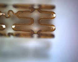
As all of the acceleration associated with cutting is performed when the linear and rotary stages are stationary, it is mainly the dynamic response of the galvanometer mirrors that will affect accuracy, and given the low mass of these mirrors, accuracy is optimized.
There are many advantages related to the sub-pattern process. However, with these advantages come tradeoffs that need to be considered. The use of a galvanometer inherently allows off-axis cutting to be performed, which can give functional benefits to many medical devices. However, for stent manufacturing it will mean that strut walls will have variations in taper. This strut taper—which means walls are no longer orthogonal—may cause issues for stent placement, which without testing may be either a positive or a negative.
Constant-rotation galvanometer scanning
A second method of employing galvo scanning technology for stent fabrication is to convert the stent vector pattern into a bitmap image and raster-scan the laser, issuing pulses at the appropriate pixel sites along each pass (see Fig. 3).1 Post-processing of the image converts the bitmap into an array of points (black-and-white or grayscale) that define the pixels.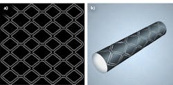
As the beam is scanned back and forth axially along the stent, the rotary stage rotates unidirectionally underneath to continue exposing the entire circumference of the stent to the scanning beam spot. One axis of the scanner (major axis) performs the linear scanning while the second axis (minor) compensates for the rotation of the workpiece during a single raster line (i.e., making sure that the line is not diagonal on the workpiece).
"Mark-on-the-fly" features native to some advanced motion controllers facilitate synchronization between the rotary stage and the minor scan axis. The rotational speed and scanning velocity are chosen such that the laser spot does not "walk off" the workpiece or become defocused.
The linear stage axis does not move at all during part processing, and the rotary stage moves at constant velocity (no acceleration). As a result, the coarse axes do not contribute to dynamic errors. The major scanner axis does not accelerate during part processing, as it reverses scan directions "off-board" of the actual pattern. The minor axis has some trivially small acceleration vector, but certainly not large enough to contribute errors on the order of servo-stage dynamics.
Increased part throughput in the face of ever-greater technical challenges must be met with new and innovative manufacturing tactics. The methods outlined here offer some new thinking on the subject and could propel the industry to exciting future growth.
REFERENCE
1. S. Schmidt, "Laser raster scanning patterns on cylindrical workpieces using advanced drawing post-processing tools," Medical Design Briefs (Jul. 1, 2015).
Scott Schmidt is group manager at Aerotech, Pittsburgh, PA; e-mail: [email protected]; www.aerotech.com, and David Gillen is managing director at Blueacre Technology, Dundalk, Ireland; e-mail: [email protected]; http://blueacretechnology.com.