Fiber For Fiber Lasers: Kagome PC fiber goes to extremes for ultrashort-pulse lasers
FETAH BENABID, FREDERIC GEROME, BENOIT DEBORD, and MESHAAL ALHARBI
The last decade has seen explosive progress in ultrafast or ultrashort-pulse (USP) lasers, whereby sub-500 fs pulse duration, high-repetition-rate, high-average-power, and up to 1 mJ pulse-energy tabletop lasers are now commercially commonplace. The exquisite micro-precision and both noninvasive and nonthermal ablation features of these USP-based material microprocessing lasers have had a transformative impact on a broad spectrum of applications ranging from existing automotive, microelectronics, and ophthalmology market sectors to emerging fields such as plastic electronics and microsurgery.1
Despite these dramatic demonstrations and potential, the integrity of USP laser light is degraded when transported to the workpiece using standard, solid-core optical fibers. Fortunately, in parallel to the USP laser advances, the field of photonic crystal (PC) fibers has also emerged as a transformative power in photonics.2 Applications of USP lasers can therefore benefit from new hollow-core PC optical fiber designs that maintain USP laser-pulse duration, beam quality, and power level through low transmission loss, high power and energy handling, low nonlinearity, and low dispersion.
Hollow-core design differences
In 2002, two types of low-loss optical fibers with very different light-guiding properties than step-index optical fibers were developed.3,4 Both fibers guide light in a hollow core surrounded by a two-dimensional periodic cladding and are thus named hollow-core photonic-crystal fibers (HC-PCFs). While both fibers share several common features, the physics underlying their light guidance-and subsequently their optical properties-differs considerably.
The first fiber was the experimental consequence of much-anticipated photonic bandgap (PBG) light-guiding technology, resulting in HC-PCFs with an absence of cladding modes at the frequencies and indices of the HC-guided modes.5 Today, our understanding and engineering of PBG HC-PCF has strongly matured with the intuitive "photonic tight-binding model".6
The second fiber, a kagome lattice HC-PCF (or just kagome HC-PCF) contrasts with a PBG HC-PCF by offering a broadband guidance spectrum and the absence of PBGs in its cladding structure. It was only in 2007 that the guidance mechanism was elucidated with the introduction of inhibited coupling (IC) guidance. Here, the cladding no longer requires a bandgap in the core mode space, but the structure and its dimensions are engineered such that the cladding supports a continuum of modes that are strongly phase-mismatched with the core modes, thus inhibiting the latter from escaping the core.
With air-silica HC-PCF, this situation can occur if the cladding modes are strongly confined in the cladding thin silica-web and exhibit very fast transverse oscillations (a high azimuthal-like number).7 In the sense that a fiber PBG is defined by the absence of phase-matched cladding modes to transfer light outward from the core, the surrounding cladding of IC guiding fibers acts as a quasi-PBG over the core mode frequency-index space.
Note that such a strong mismatch can occur even if the cladding and core modes have the same effective index. This model is akin to that of a bound or quasi-bound state in a continuum predicted by Von Neumann and Wigner within the context of quantum mechanics or condensed matter physics. Thus, a kagome HC-PCF is the first photonic manifestation of a bound or quasi-bound state in a continuum.
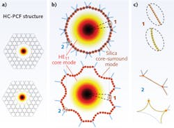
More importantly, the model provides strong predictive tools that led us to the development of a hypocycloid-like (or negative curvature) core-shape HC-PCF (see Fig. 1).8 This core shape enhances IC guidance compared to a circle-like contour, which was the shape for conventional seven-cell HC-PCF.
Hypocycloid kagome
The hypocycloid contour exhibits a set of alternating negative curvature cups with an inner radius Rin and an outer radius Rout. For this contour, the fundamental mode of the HC is that of HE11, and its mode-field diameter is that of a capillary or a circular-core HC-PCF with a radius equal to . Based on this fact, the overlap integral between the core mode and the highly oscillating (high azimuthal-like number m) silica core-surround mode (cladding mode) is strongly reduced via three avenues.
First, via a simple spatial overlap reduction argument, at the circle of radius, Rin, the core HE11 mode transverse profile intersects with only the tangent sections of the six most inner cups for the hypocycloid contour, while the profile intersects with the whole circle perimeter in the case of the circular contour.
Second, the IC is enhanced by a symmetry argument. Because of the larger perimeter of the hypocycloid, the silica core-surround modes exhibit higher m and by virtue of a stronger transverse phase-mismatch, Δβ⊥∝m, the overlap integral between the core mode and the cladding mode is further reduced.
Finally, the IC is enhanced by reducing the overlap between the core mode with the low-azimuthal-number modes residing at the connecting nodes. Indeed, the connecting nodes, which are inherent from the HC-PCF structure and fabrication process, are "pushed away" from the core mode with the hypocycloid contour. By this simple and intuitive picture, one can expect a further enhancement in IC and hence a stronger reduction in confinement loss.
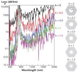
By increasing the negative curvature of the inner cups, which is quantified by the parameter b, confinement loss decreases from 1 dB/m in a circular core to < 1 dB/km for the hypocycloid contour with b larger than 1 (see Fig. 2).9 Furthermore, high-order mode (HOM) propagation loss increases with increasing b, favoring single-mode operation for large negative curvature.Numerical calculations also show a strong reduction in the optical overlap of the core mode with the cladding, bringing it down from the 10-4 level for a circular core contour to the 10-6 level for a hypocycloid contour with b > 0.5. In order to put these figures into perspective, the PBG HC-PCF optical overlap with the cladding is on the order of 1%—a reason why PBG HC-PCF is not suitable for high-power USP guidance.
USP-guidance advantages
The negative curvature of the fiber core contour allows a dramatic reduction in transmission loss in IC-guiding HC-PCF, improved single-mode guidance, and ultralow optical overlap with the surrounding silica core surround. Within this context, hypocycloid core-contour HC-PCF outperforms PBG HC-PCF, exhibiting a spectral bandwidth that can span several octaves-including spectral ranges where silica strongly absorbs.
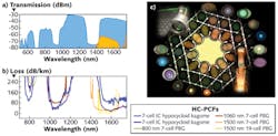
Today's hypocycloid kagome HC-PCF has the lowest loss figure in the near-infrared through visible spectral range with a record 17 dB/km at ~1 μm and 70 dB/km at around 780 and the 500-600 nm wavelength range.
In the 1500 nm window, kagome fiber loss of 30 dB/km is comparable to that of a seven-cell PBG HC-PCF (see Fig. 3). Such loss figures are also obtained in the infrared when only a single ring is used for the cladding structure. Our group has demonstrated this with an acetylene infrared laser, and other groups have coined this fiber as a negative-curvature hollow fiber. Indeed, our flexible fabrication processes allow us to manufacture a variety of kagome optical fibers.In addition to fabricating hypocycloid kagome HC-PCFs for ultrahigh-power USP guidance and delivery, kagome fiber also has low waveguide dispersion and anomalous group velocity dispersion (GVD) over a large portion of its transmission bandwidth—attributes of a very good pulse compressor.
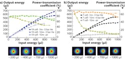
The large dynamic ranges of dispersion and nonlinearity control that can be achieved by simply changing the fiber core diameter, its cladding, and/or by introducing an active gas at a given pressure inside the fiber core renders kagome fiber a unique platform for high field optics. For example, USP transportation and compression in hypocycloid kagome HC-PCF has been demonstrated, with USP energy levels10 reaching 1 mJ when 600 fs pulses emitted from an ytterbium laser are coupled to two different types of kagome hypocycloid fibers (3 m and 10 m lengths) with a b parameter close to 1 (see Fig. 4). The first HC-PCF is a 19-cell hypocycloid-core kagome HC-PCF with an inner core diameter of 80 μm. The second is a seven-cell hypocycloid-core kagome HC-PCF with an inner diameter of 55 μm.Finally, and to further demonstrate the flexibility of these fibers, the GVD at the laser wavelength (1030 nm) was set to be anomalous in the first fiber and normal in the second fiber. The transmission measurements were undertaken when the fiber is exposed to ambient air (air-filled) and when the core is filled with helium (He-filled) to reduce the nonlinearity and increase the ionization intensity threshold. The results show that more than 80% of the transmission coefficient is achieved in He-filled HC-PCF, and a maximum of 700 μJ is transmitted when the input energy is 1 mJ. The output beam profile remains that of a single HE11 mode, and the fiber's structural integrity is undamaged despite the fluence being orders of magnitude larger than that of the silica catastrophic damage threshold.
All transmission curves show a slight drop in the transmission-coefficient slope, which is due to the onset of gas photoionization effects on linear fiber guidance. Such an effect could be further reduced by lowering the He pressure or by evacuating the fiber. It should be noted that the transmission coefficient has been improved to more than 90% with the use of better-matched coupling lenses.
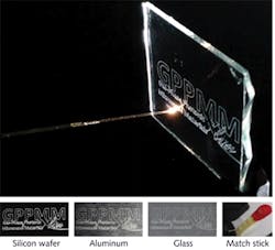
When USP transport with no distortion is required, pulses in air-filled 19-cell HC-PCF go through solitonic spectral dynamics with a self-compression down to less than 49 fs at an input energy of around 0.45 mJ. Finally, with He-filled seven-cell HC-PCFs, the spectral dynamics are chiefly dominated by self-phase modulation broadening. This effect, however, has been kept to a low level, and thus the pulse compression remains moderate. It is worth mentioning that these 600 fs pulses had GW peak power and close-to-PW-per-cm2 intensity, recalling the high field regime where these results are obtained.Another salient result is the demonstration of material micro-engraving with USPs delivered via a 10-m-long He-filled seven-cell HC-PCF. In a manner similar to pen writing, our logo was engraved with USP light delivered directly from the output fiber tip (see Fig. 5). Engraving was demonstrated on different materials to demonstrate the cold ablation regime under which this materials microprocessing function is undertaken.
Acknowledgments
The authors are grateful to their colleagues Luca Vincenti and Eric Mottay, and to the Amplitude Systemes (Pessac, France) and GLOphotonics teams.
REFERENCES
1. M. Mielke, Laser Focus World 49, 11, 35–41 (2013).
2. P. Russell, Science 299, 5605, 358–362 (2003).
3. F. Benabid et al., Science 298, 5592, 399–402 (2002).
4. N. Venkataraman et al., Proc. ECOC 2002, PD1.1, Copenhagen, Denmark (2002).
5. T. Birks et al., Electron. Lett. 31, 22, 1941–1943 (1995).
6. F. Couny, Opt. Express 15, 2, 325–338 (2007).
7. F. Benabid et al., Laser Focus World 44, 9, 60–64 (2008).
8. Y. Wang et al., OSA Technical Digest for CLEO 2010, postdeadline paper CPDB4 (2010).
9. Y. Wang et al., Opt. Lett. 36, 5, 669–671 (2011).
10. B. Debord et al., Opt. Express 21, 23, 28597–28608 (2013).
Fetah Benabid is CNRS research director and Gas-Phase Photonic and Microwave Materials (GPPMM) group leader within the Xlim Research Institute at the University of Limoges, France; email: [email protected]; www.xlim.fr/en/gppmm. Benabid is also chief science and technology adviser at GLOphotonics, Limoges, France. Frederic Gerome is CNRS research officer and GLOphotonics scientific adviser; Benoit Debord is a research officer at the GPPMM group; and Meshaal Alharbi is a PhD student at the GPPMM group.
