Communication is the key to effectively carrying out optical design projects while shortening design cycles and reducing manufacturing costs because it enables the customer and the designer to work as a team to identify tradeoffs that can be made to save time and money without sacrificing the effectiveness of the design. The following communication guidelines come from notes taken during a tutorial "How to Talk to a Lens Designer." John Rogers, director of photonic and imaging engineering services at Optical Research Associates (Pasadena, CA), presented the tutorial at an OSA annual meeting several years ago. But the information is just as pertinent now as it was then.
To get the process started, the customer must first clearly identify and list the specifications (must haves) and goals (like to haves) for a project. Background information on the specific application may also be helpful in allowing a designer to draw on previous experience. Designers often have generic specification sheets that the customer can procure and fill out beforehand, which can be a big help for designers.
"At ORA, we organize the ongoing communication process by breaking the project into phases with a design review for each phase along the way," Rogers said. A feasibility or conceptual design study at the beginning can be particularly helpful in identifying possible tradeoffs that the customer may not be aware of, since there are often few hard specifications and many goals at the outset. The early review is also the best time for a fundamental reality check on the project, where questions such as "Can we get there?" or "Is the ballpark big enough?" need to be answered definitively and in the positive before proceeding.
Subsequent to the conceptual review, a preliminary review should produce a rough design with enough detail to enable the customer to contact manufacturers. A preferred system configuration (number of elements and so on) should be identified, a rough estimate made of tolerance sensitivity, and—in terms of deliverables—a revised specifications table should be completed with all goals replaced by achievable specifications. The design layout should be rendered with enough accuracy to allow manufacturers to give rough cost and time estimates.
A final design phase (with support of preferred or chosen manufacturers) would consist of matching design specifications and tolerances with actual manufacturing capabilities, and adjusting and trading off of specifications, tolerances, and at-assembly compensators as necessary to come up with a prescription that will meet the customer's need and that the manufacturer says can be built.
Fabrication and assembly constraints that a customer should expect to encounter include the grade of the optical glass to be used, tolerances on radii, thickness, and wedge during fabrication and tilt and decenter at assembly. When considering manufacturing-related tradeoffs, one effective technique is to use reasonably loosen tolerances on the individual elements, but plan on making some adjustments ("compensations") to the system after the system is assembled and tested.
However, different tolerances affect cost in different ways for different manufacturers, and it can sometimes be less expensive to go with tight tolerances and no compensators if working with a high-precision shop. Performance specifications can be met in some cases by using multiple compensators, or by controllable factors in assembly or alignment steps. In all cases, however, the designer needs to be made aware of either the manufacturing constraints or the performance specifications that are not negotiable.
Keep it simple
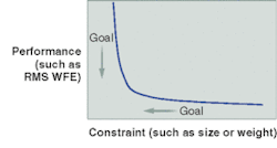
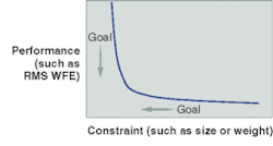
Rogers summarized his talk with four points, and the first three—give a designer all necessary information, know what's firm, and know what's flexible—have been discussed above. The fourth step, finding the knee of the design curve, is much more project-specific, but Rogers offered numerous examples of how parameters can be chosen to enable a customer to position the product optimally in the performance/cost space (see figure). It is often the case that what the customer needs (or at least wants) is either not possible or only possible at an excessive cost. In the end, the customer must make the trade between performance and cost. But the designer can support the customer by examining a few locations in the design space.
In balancing performance specifications (such as root-mean-square wavefront error) against physical constraints, (such as size, weight, object/image distance, and pupil clearance/eye relief) for the most time- and cost-efficient design, the ultimate goal is to get as close as possible to the knee of the design curve. "Many applications behave in the manner indicated in this graph," Rogers said. "In such cases, the appropriate action is to search for the point where things begin getting difficult rapidly, and readjust the goals accordingly."
Three basic component groups determine the complexity of any optical design: sources, optics, and detectors, he said. Sources range in coherence, complexity, and expense from light bulbs to lasers. Optics can range in size from endoscopes to space telescopes and they can range in environmental design requirements from underwater to outer space. Detectors can range from the as-is human eye to an off-the-shelf or custom-built camera.
In considering optics, for instance, Rogers stressed the need to avoid overdesigning, noting that design difficulty is a nonlinear function of numerical aperture. The optical or Lagrange invariant offers a measure of design complexity and quantity of information, he said. The numerical value of the invariant can be calculated in several ways—one of which is to multiply the image radius by the numerical aperture—and once calculated for a given surface in the system, it remains invariant (except in the case of nonimaging systems, which involve diffusers) throughout any continuous part of an imaging optical system. Parameters that can often be determined using the invariant include magnification, image height for an object at infinity, telescopic magnification, value of any third ray in a system based on known data from two traced rays, focal length, and location of entrance pupil.1
To avoid overspecifying spectral range and weights, Rogers recommended factoring in the responsiveness of the detection system, the transmissivity of the system, and the spectrum of the source. To find areas where design is actually needed for visualization by human observers, Rogers recommended multiplying retinal photopic or scotopic response by the solar spectrum. The resulting curve is much narrower than the "400 to 700 nm" spectral band that customers often request.
"Generally when people say they want uniform weighting over the spectrum in general, that is not what they really need, and it will make their system much more expensive," Rogers said. "So more specifics are needed to save money and to have a more practical design." Even in applications in which a CCD replaces the eye, the responsivity peaks in the near-IR, and the responsivity in the blue is much reduced. So the design can often be simplified by taking advantage of this.
Of course, the actual tutorial went into much more detail than can be presented here in terms of both overall communication guidelines and specific examples related to developing practical and useful performance specifications. For more information, contact John Rogers at [email protected].
Reference
- W. J. Smith, Modern Optical Engineering (Third Edition), pp. 49–54, McGraw-Hill (2000).

