Vertical-cavity Surface-emitting Lasers: VCSEL arrays provide leading-edge illumination for 3D sensing
A new area of laser applications is developing that could bring lasers into every phone, car, and household. Smartphones, laptops, drones, robots, and cars increasingly embed functions to map the 3D space around them, for reasons of navigation, augmented reality and/or virtual reality (AR/VR), or identification. All these devices require new sensors onboard, providing a measurement of the distance to the objects in their environment and hence creating 3D environmental data and maps.
Applications range from proximity sensing in phones and observation of humans and objects in a few meters distance, up to light detection and ranging (lidar) systems in autonomous cars resolving small obstacles more than a hundred meters ahead. Laser-based measurements are the method of choice, combining high accuracy with a compact form factor. The wide field of applications and the consumer nature of most markets make vertical-cavity surface-emitting lasers (VCSELs) a good laser source for providing the illumination in 3D sensing.
In this approach, distance is determined by measuring the traveling time of light emitted from a laser source, reflected from an object, and finally received by the sensor. So-called direct time-of-flight systems use short laser pulses and sensitive detectors such as single-photon avalanche diodes (SPADs) to determine the traveling time directly. Indirect time-of-flight systems measure the phase shift between the emitted and the received pulse train and are available on camera chips, allowing approximately QVGA lateral resolution.
The competition with photons emitted continuously by the sun or artificial light sources is the major limitation of the time-of-flight technique in practice. Spectral filters in front of the sensor and centered around the laser wavelength can suppress this background-the narrower the bandwidth, the narrower the laser spectrum can be made.
VCSELs are simple, stable
VCSELs are becoming the dominant light source technology for 3D sensing and can replace LEDs or edge-emitting laser diodes because they are simple, have a narrow spectrum, and are stable with respect to temperature.
A VCSEL is produced in a single epitaxy process, providing on a substrate a first distributed Bragg reflector (DBR) mirror, a multiple-quantum-well (MQW) structure with current confinement, and a second DBR mirror. Both mirrors conduct the current from metal contacts deposited on the surface of the structure towards the active region. Millions of VCSELs can be produced on one gallium arsenide wafer and are all completely tested before separating them into single chips.
Individual VCSELs are limited in size (10 μm emitting diameter) and output power (10 mW), but scalable into densely packed arrays with tens to thousands of VCSELs on a single chip, enabling high-power devices (see Fig. 1). The emission pattern is circular, with about 20° full width at the 1/e2 points and with all VCSELs in an array superimposing in the far field. Optical elements can easily be stacked on top of the VCSEL chip to collimate or to shape the emission pattern.
The spectral width of the VCSEL array emission is only 1–2 nm. Add the small wavelength spread from production and the thermal shift of the wavelength of only 0.065 nm/K, and the result is a small spectral window that enables efficient background suppression by a simple filter in front of the sensor. The laser resonator that is defined by the two DBRs ensures a very narrow and stable emission when compared to the wide spectrum of LEDs and the fivefold-larger thermal shift of LEDs and edge-emitting laser diodes. A VCSEL-based system needs significantly less power in the same application, as the background can be reduced more effectively.
Some technical particulars
Many applications are best served by a wavelength of 940 nm rather than 850 nm, as the background from the sun is lower, the red glow becomes less visible, and silicon CMOS sensors are still sufficiently sensitive at the longer wavelength. The measurement shown in Fig. 2 demonstrates the good stability of wavelength and power output over a wide temperature range of -30° to 110°C.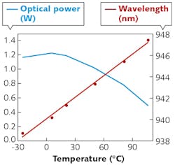
Time-of-flight measurements require short pulses of 1 to 10 ns or pulse trains with modulation up to and above 100 MHz. VCSEL arrays are well suited for fast switching—we have demonstrated rise and fall times <1 ns, even at array areas on the order of a square millimeter and currents of many amps. While the VCSEL array itself allows pulses <0.1 ns, electrical connections to the driver and impedance in general are the limiting factors for pulse length.
Short pulse operation at low duty cycle pushes out the limitations posed by self-heating in continuous-wave (CW) operation. When pulsed, relatively small chips can operate at much higher currents and peak power than in CW mode. Figure 3 shows a measurement of increasing power per single mesa with shorter pulse duration. An array of 500 to 1000 mesas can emit several tens of watts from a 1 to 2 mm2 area.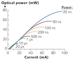
VCSEL-array chips can either be assembled directly into the sensing system or provided in a separate package for a surface-mount device (SMD) configuration. An example of such a packaged product from Philips Photonics is shown in Fig. 4 with outer dimensions of 3.7 × 3.7 × 1.9 mm3, capable of emitting 2 W CW optical output power and much more in pulsed mode. The VCSEL chip has an emission area of 1.5mm2 and may contain a diffuser used to provide high-uniformity illumination over the desired field of view. The diffuser can be tailored to enhance the center or the edges of the field and to distribute the emitted light across large angles up to more than 100°. The individual VCSELs in an array are mutually incoherent, thus reducing speckle patterns. The package in Fig. 4 is hermetically sealed and fits the strict needs of automotive applications.
The emission of 2 W average laser power calls for an analysis of laser safety. The radiation is spread by the diffuser over a considerably large cone, with the brightness of the individual VCSEL facets averaged over the whole area. Owing to the nature of such an extended source, this laser, classified according to IEC 60825-1:2014, could also be classified in the same way as an LED according to IEC 62471-1:2006. Although it would be possible to apply this less-restrictive regulation, we nevertheless design products according to the more-restrictive laser safety regulation. With it, an average emission of 18 W from the product as described in Fig. 4 is considered eye-safe. This is significantly above the maximum emission power of the device—as a result, eye and skin safety are guaranteed under this norm.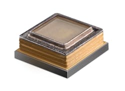
Because of their many technological advantages, VCSEL arrays are very well suited for time-of-flight distance-measurement applications, giving high peak power in short pulses and a narrow optical spectrum. Future VCSEL developments will expand these advantages even further:
- Arrays can be arranged into multiple segments by straightforward mask layout—this feature will be a necessity for next-generation 3D sensing systems;
- VCSELs allow for wafer-level integration of optical elements that will drastically reduce assembly efforts; and
- With the use of an extended cavity, the brightness of a VCSEL array can be increased by more than a factor of a thousand, enabling scanning lidar in automotive applications.
About the Author
Holger Mönch
Senior Expert of Product Management, TRUMPF Photonic Components
Dr. Holger Mönch is senior expert of product management at TRUMPF Photonic Components (Ulm, Germany).