Tunable Filters: Wavelength filtering technology improves spectral imaging
JUN HEE KANG and CATHY FITZPATRICK
While spectral-imaging applications have advanced tremendously over the past two decades because of improvements in detector technology, they are still hampered by the limitations of legacy wavelength-filtering/dispersion technologies. For example, scientific imaging was revolutionized by the replacement of photomultipliers and single-point scanning with low-noise, two-dimensional (2D) arrays (CCD and, later, sCMOS) detectors. Similarly, machine vision long ago switched from fast-scanned vidicon technology to solid-state cameras.
However, wavelength filtering is still performed using individual filters or filter wheels, or with grating- or prism-based monochromators. This situation has now changed with the introduction of a new approach having a simple concept.
Spectral imaging: fluorescence microscopy
Spectral imaging can take many forms and serve multiple purposes. It records image-intensity maps as a function of location (either x, y or x, y, z), as a function of one or more wavelength parameters, and often as a function of time. Its applications are wide-ranging and diverse. For example, they include satellite mapping of weather, drought, and agricultural resources; machine vision for automobile painting; quality assessment (for example, ripeness) of natural products; analysis of structured pharmaceuticals; medical imaging; and scientific research, often in the form of fluorescence microscopy. Within all these broad categories, there are many variations in form and purpose. These can be broadly classed as mapping/confirming the content of the sample, or identifying/confirming the location of a specific content within the sample.
Fluorescence microscopy provides an excellent example of an application that has advanced with imaging and reagent technology, yet still remains constrained by wavelength-filtering limitations. The advent of array detectors nearly 30 years ago enabled microscopes to rapidly acquire high-resolution images and, thus, follow intracellular processes in real time. Similarly, reagents have advanced from a handful of fluorescent stains applied to fixed (in vitro) samples to an ever-widening range of fluorescent probes. These include those that preferentially attach to specific biochemicals (such as lipid membranes or nucleic acids), as well as functional probes whose fluorescent response varies according to local conditions such as calcium ion (Ca2+) concentration, pH, or membrane potential. And, of course, there is a whole arsenal of genetically expressed fluorescent markers, from GFP and the mFruit series, to functional probes, such as the genetically expressed calcium indicator (GECI) family.
All these probes have a characteristic absorption and emission spectrum. So, by wavelength-filtering the fluorescent images from samples containing these probes, the content, structure, and behavior of biological samples can be studied with true multidimensional interrogation. Some fluorescence-imaging methods (such as first-generation confocal microscopy) scan the sample point by point and are well served by existing filtering technologies. But a large proportion of fluorescence-microscopy techniques employ an array camera. It is therefore advantageous if the method used to wavelength-filter the light reaching the camera can be rapidly switched or scanned in wavelength, and also that it cover the full field of view of the imaging system.
Limitations of existing technologies
There are several technologies that have been used for spectral filtering on the detection side of fluorescence microscopy and other spectral-imaging applications.
The monochromator disperses light as a function of angle using a diffraction grating or, sometimes, a prism. By using an input and output slit, the monochromator can be used to select a single narrow-wavelength band. The center of this band is then scanned by rotating the grating. Alternatively, a detector array replaces the output slit and enables up to 2048 different wavelength channels to be sampled simultaneously.
The primary advantages of the monochromator are the flexibility of the wavelength dispersion (in terms of both scanning and bandwidth control) and the high amount of band blocking (extinction), which can be several orders of magnitude. The main disadvantage for spectral imaging is that the monochromator separates light as a function of angle or, more specifically, the x displacement in the detector plane. This leaves only the y axis available for spatial discrimination. Therefore, 2D images are built up line by line or the monochromator is used to filter light from a single point, which must then be scanned in the sample, as with early confocal microscopy. In addition to the complexity required, speed is obviously an issue here, with a tradeoff between field of view and frame rate.
Individual filters, or a wheel of separate filters, are another method used in many applications, particularly in microscopy. These coated glass filters can be of the bandpass, notch, or cut-off type. The advantages are the low cost, particularly in OEM quantities, and the large clear aperture, with uniform wavelength response across the entire aperture. This makes filters highly compatible with 2D imaging methods. Their disadvantage is a complete lack of flexibility and scanning-the wavelength characteristics are fixed, and they are best used to image a specific spectral window.
There are also linear (and circular) variable filters, in which the spectral response changes with position across the filter. Thus, these act rather like a monochromator—when the filter is moved in front of the image, wavelength varies according to distance along one axis, leaving only a single axis for spatial information. These devices are more commonly used for compact spectrometers rather than for spectral imaging, although they are sometimes used with line scan cameras in machine vision.
The acousto-optic tunable filter (AOTF) is another wavelength discrimination device. It is a solid-state component based on an exotic crystal such as tellurium dioxide (TeO2). Radio-frequency (RF) power is applied to one side of the crystal, setting up a fast-moving acoustic wave. This acts as a moving diffraction grating so that only input light of a certain wavelength is diffracted towards the output aperture.
For spectral imaging, the main advantage of the AOTF is that it has a square or rectangular aperture that can be used for direct imaging. However, it has numerous well-documented drawbacks. First, it is a complex RF-powered system that is relatively costly. Plus, this cost increases nonlinearly with aperture size. The AOTF also has poor out-of-band extinction, typically <102. In addition, there is a fixed relationship between bandwidth and center wavelength, and in many devices, the output angle shifts with wavelength.
New approach based on angle of incidence
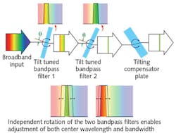
A technology called TwinFilm provides the wavelength flexibility and precision of a monochromator with the large clear-aperture advantages of a filter (see Fig. 1). Recent advances in ion-beam sputtering (IBS) have enabled the fabrication of bandpass filters that combine a broad transmission band with very sharp edges and high (up to 10-6) out-of-band extinction. TwinFilm technology combines two of these broadband bandpass filters in a compact, light-tight housing in an arrangement that enables independent rotation of the angle of incidence of each filter (see Fig. 2).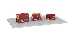
These bandpass filters are all-dielectric, with transmission/reflectance characteristics determined solely by interference between the multiple coating layers. But the center wavelength of each filter shifts as the angle of incidence changes, so for collimated input light, rotating the angle of incidence of one of these filters serves to smoothly tune its transmission spectrum. And, because there are two of these filters, they can be used to independently define the short- and long-wavelength edges of the overall transmission curve. In this way, both the center wavelength and bandwidth of the transmitted light from any collimated source are fully adjustable. Just as important, a third glass plate is simultaneously rotated to offset any slight lateral walk-off in the beam path as the angles of incidence are set or swept.
The bandwidth of TwinFilm products can be user- or factory-adjusted anywhere between 1.5 and 20 nm, and the center wavelength can be chosen to be at virtually any visible wavelength (350–900 nm). Moreover, because they work with collimated light, the infinity space (the collimated space) in a microscope is an ideal location for compact devices based on this technology. In addition, the collimated input/output allows for simple fiber coupling, as is already offered in some commercial devices based on this technology.
This construction gives TwinFilm filters several key advantages. Like a grating-based device, the out-of-band extinction is very high (10-6). But, like a traditional filter (and unlike a grating monochromator with a narrow slit geometry), the spectral performance of a TwinFilm device is uniform across 95% of the large (up to 10 mm diameter) clear aperture. These characteristics make it well suited for spectral filtering in imaging applications.
Automated, manual, and custom-select wavelengths
Currently, there are three different embodiments of this core technology. These provide automated wavelength scanning, manually adjustable wavelengths, and custom-select fixed-wavelength characteristics.
The greatest functionality is provided in the form of a flexible wavelength selector, which is equivalent to a fully featured monochromator, but with a large, uniform imaging aperture. Here, rotation of the internal optics is motorized, and all control is via USB interface through software with a user interface (as well as through a set of serial commands). The center wavelength can be scanned (or set) with a resolution of ±0.1 nm, and the bandwidth can be varied from 1.5 to 20 nm. This type of device will enable researchers to fully optimize every spectral-imaging application, particularly those involving new fluorophores or varying background matrices, such as new fluorescent proteins, medical imaging, and natural products such as fruit.
This automated wavelength tuning can be used to acquire near-simultaneous microscope images of multiple fluorescent labels (see Fig. 3). This simple example shows HeLa cell images optimized for DAPI and Dil. This type of imaging would normally require either some type of filter wheel or else multiple cameras, each with a different bandpass filter.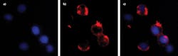

In another product implementation, manual wavelength tuning and bandwidth adjustment are performed using two small knobs. This lowers the package cost and size for applications requiring a settable wavelength rather than a smoothly scanned or stepped wavelength. And, in a third and even smaller format, there are no adjustments, and the angles are all factory-set and fixed. This enables immediate shipment of custom-select bandpass performance.
Jun Hee Kang is an application scientist and Cathy Fitzpatrick is vice president of sales and marketing, both at Spectrolight, Irvine, CA; e-mail: [email protected]; www.spectrolightinc.com.