Motion Control: Accuracy and precision rule pan-tilt positioners in critical camera applications
LISA GERBRACHT and KAI MONCINO
Positioning systems with high precision and accuracy are critical to successful remote monitoring and video tracking systems. whether the application involves tracking airborne objects, building an accurate image database for a construction site, or spotting and identifying a potential threat with an unattended ground sensor. Although pan-tilt positioning systems satisfy many critical camera applications, some common misconceptions about positioning accuracy, repeatability, and precision require clarification.
Positioner basics
Pan-tilt positioners are two-axis motion control devices used to point sensors and cameras and often track objects in real time. The sensor is mounted to the pan-tilt positioner and an operator or a computer controls the speed and position of the pan and tilt axes to keep the sensor pointed at the target.
When camera and/or sensor system designers select a pan-tilt positioner, payload capacity, size, and cost are all important. If it's important for the camera to target an exact location when commanded, such as a camera following an unmanned aerial vehicle (UAV), positioning accuracy becomes paramount. It must be carefully considered by the system designer, especially when working with narrow-field-of-view (FOV) sensors that perform remote monitoring or video tracking. For example, a 4° × 3° FOV sensor for detecting vehicle targets at a distance of 6000 m requires increased accuracy. At that range, a positioning error of 0.04° can result in the target being missed.
Accuracy is a measure of how close the pointing angle is to the commanded angle. If a camera system is commanded to point to a location defined by an angle of 90° to the left, and the pan-tilt positioner has an accuracy specification of ±0.05°, then it will actually point somewhere in the range of 89.95 or 90.05°—even if it is reporting an angle of exactly 90°.
Repeatability and accuracy, in this context, are closely related: accuracy is consistent pointing in relation to some universal datum, while repeatability is the consistent return to a fixed point. In the case of a security camera returning to a specific location within a region of interest such as a security checkpoint in an airport, the typical pan-tilt repeatability value is 0.1° for a travel range of 180°.
Calibration of the system to an external location using GPS coordinates or some other method enables users to determine true pointing accuracy. In the absence of external calibration, it is logical and acceptable to refer to the repeatability of the pan-tilt positioner.
Angular resolution is the minimum step size that the pan-tilt system can move. For a high-performance pan-tilt unit, minimum step-size values on the order of 0.003° are possible. For low-cost pan-tilts, minimum step sizes of 0.1° are typical. Some pan-tilt units have adjustable resolutions that are achieved by micro-stepping the motors.
Increased resolution "smooths" motion and is particularly useful for long-range imaging applications, such as detecting vehicles or people from 1 km or more for border security. If the pointing resolution of the pan-tilt system is not sufficient for the application, there may be regions the sensor or camera cannot cover. This becomes more extreme as range increases, as a certain angle of motion equates to a longer radial distance at range.
Pointing-error contributions
Pan-tilt systems are complex electromechanical devices. Their components all affect pointing accuracy and repeatability, including gears, belts, and reducers that wear over time; homing or calibration systems that rely on limit sensors; and housing or drive system rigidity that contribute to error.
If the pan-tilt repeats the same pattern in both axes on a predetermined scan list, the preset locations will always be approached from the same direction. Pointing error from backlash or gear wear may not be evident, as the gears are always pre-loaded to the same side.
Applications requiring frequent direction changes while tracking moving objects may experience larger pointing errors in the same system. In addition, applications involving pointing in high gusty winds will expose errors from backlash in the pan-tilt system.
The repeatability of a pan-tilt system can be observed if a target is approached first from one direction and then from the other. For example, if the system is commanded to point to 90° in the pan axis, it may approach from either the left or the right. Any mechanical compliance or backlash in the gears will contribute to the pointing error.
If errors are occurring in more than one axis, then the overall error could be larger. Consider if the error in one axis is 0.15° and the error in the other is 0.1°, the reported position may be off by 0.18°, which is the length of the hypotenuse (a2 + b2 = c2). Uneven wear or runout can also contribute to inconsistent pointing accuracies across different areas of the axis.
Systems used in scientific research may require correlation of position data from the pan-tilt positioner with sensor data from the payload. These data are collected using a laser rangefinder or GPS, which can be highly accurate. However, if the pan-tilt system is constantly scanning and reporting position data at a rate of 30 Hz or more, system latency can contribute to perceived error. This is because the pan and tilt axes move before position and speed information has time to reach the user. With axis speeds of 120° per second or higher, this perceived error will increase.
Timestamping of pan-tilt position and speed data can compensate for latency errors. FLIR pan-tilt position and speed data can be reported with internal clock data from the controller board, which runs at 90 MHz.
Application challenges
Pan-tilt positioners are commonly used for remote monitoring of construction sites, fields, or critical infrastructure. When the system is automated, meaning an operator is not controlling the speed and position, its success depends on the ability of the unit to point where it has been commanded.
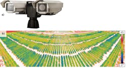
In agricultural applications, such as monitoring crop canopy temperature, a database is built from collected images to track temperature changes over time and identify areas that need attention (see Fig. 1). A high degree of pointing error in the pan-tilt positioner makes it impossible to properly stitch together images or correctly reference locations. Similar systems for construction-site monitoring also require a high degree of repeatability-the ability to return to the same location every time.
Pointing accuracy is also critical for video tracking systems needed to accurately target moving objects such as UAVs or drones (see Fig. 2). Here, a camera system with one pan-tilt video tracker detects and locates the drone and a second pan-tilt system with a frequency jammer disrupts communications. In a system with pan-tilt units for both the video tracker and the jammer, speed accuracy is critical. The speed at which the camera tracks the drone must be correct, or the system may not follow it properly. The slaved pan-tilt must also receive the correct speed information and respond accordingly for the jamming system to be effective.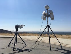
For unattended ground sensor applications, cameras mounted to pan-tilt positioners are triggered to turn on and slew as quickly as possible to a target location identified by a sensor such as radar. Cameras used in this application often have narrow fields of view to provide higher-resolution images at longer ranges. While the image is superior, there is a higher risk of losing the target due to calibration or positioning errors.
Improving accuracy and repeatability
Many motion control applications are not particularly susceptible to problems with pointing accuracy or repeatability. If the sensor has a wide field of view, small positioning errors are not noticeable. There may be a human operator with a joystick who unconsciously corrects for small errors. However, for applications where accuracy and repeatability matter, the pan-tilt component can make a huge difference. Such applications include correlation of sensor data to pan and tilt angles, quick movement of camera payloads to indicated locations, and the development of image databases that must match up days, weeks, or even months later.
One way to ensure good pan-tilt repeatability is to include a feedback system. This can be accomplished with potentiometers, resolvers, or encoders.
Potentiometers are devices that measure angles based on variable resistance. This resistance can change with time and temperature, so potentiometers are not as accurate as other feedback methods. Their repeatability typically about 0.25°.
Resolvers consist of a rotating element inside a fixed element, generating two sine waves. By measuring the phase difference of these two sine waves, rotational position can be determined. The analog signals must be digitized and processed to be used in a computer controlled pan tilt, which can limit the accuracy—usually to 0.1°.
Encoders work by providing discrete pulses or position counts. Optical encoders detect light as it is transmitted through the encoder disk, and the pattern of lines on the encoder disk indicates the rotational position. Accuracies of 0.05° or better are possible with this method.
Encoders on the back of the motors can catch motor cogging or slip events, but they don't detect issues with compliance or backlash in the gears. Encoders on the output shaft allow the system to correct for pointing errors because of compliance, including backlash. For FLIR pan-tilt systems such as the PTU 5, encoders on the output enable pointing resolution and repeatability values of 0.01° and ±0.05°, respectively (see Fig. 3).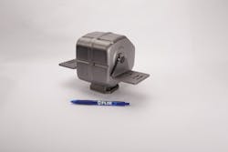
There are other ways to overcome positioning errors in pan-tilt systems. The gears can be pre-loaded to one side, either by adding an external spring or mounting the sensor off-balance on purpose. This allows any spaces in the gear mesh or any other compliance in the system to be removed. The system can also be programmed to move primarily in one direction, allowing it to approach each target from the same direction every time, minimizing the effect of any compliance or wear in the system. And finally, the system can be programmed for small delays after completing a move to allow for payload oscillations to subside.
Besides repeatability, methods to improve pan-tilt accuracy would involve the use of an external sensor, such as GPS, to correlate pan-tilt angles with actual targets. A calibration would be required during setup to teach the system its position and heading, and to perform the coordinate transformation between pan-tilt angles and GPS locations.
Lisa Gerbracht is OEM sales manager and Kai Moncino is a mechanical engineer, both at FLIR Systems, Goleta, CA; e-mail: [email protected]; www.flir.com/mcs.