Optical Design: Simplify optomechanical design while eliminating STEP files and ray bundles
CORT STINNETT and ANDY FERRIS
Optical and mechanical engineers must work closely to turn an optical system design into a real product. Unfortunately, the transition between optical and mechanical design phases is costly and error-prone. Many problems that engineers must solve are difficult to address using existing workflows and design strategies.
Optical and mechanical engineers frequently work in disparate design software environments using tools that lack integration. Although the toolbox for optical engineers has expanded, mechanical engineers have been left behind, without the tools to analyze and validate the impact of mechanical geometry on optical performance, evaluate optomechanical tolerances, optimize mechanical designs for multiple configurations, and/or perform structural and thermal deformation analysis.
Robert Mentzer, optical engineer at Global Surgical Group (St. Louis, MO), says, "As we prepare an optical design for packaging, we have mechanical engineers in mind. Even so, during handoff we encounter challenges in communication." The result is often delays, unnecessary design iterations and validation bottlenecks, and costly production of numerous physical prototypes to identify problems.
Speaking the same language
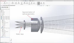
Preserving the integrity of optical data when transitioning from optical to mechanical designs can pose a serious challenge for companies. The common practice is for mechanical engineers to import optical systems into Dassault Systemes' SOLIDWORKS as STEP, IGES, or STL files, and to rely on ray bundles to provide approximations of light propagation (see Fig. 1).
This technique often introduces inaccuracies that corrupt the design for several reasons:
- STEP, IGES, or STL files degrade the accuracy of optomechanical designs, and optical tolerances, coating types, and material data are lost during file conversion;
- Ray bundles are imported as static sketches that represent a very small sample of the actual rays used in the optical analysis and cannot be updated with design changes; and
- Mechanical engineers rely on optical engineers to validate designs or build costly, time-consuming physical prototypes to identify design problems.
Mechanical engineers also lack a quick or accurate way to check that the mechanical geometry does not impact optical performance. Even subtle changes to the mechanical geometry, or inaccuracies from poor optical data integrity, can significantly impact optical performance.
When mechanical engineers send STEP files back to the optical engineer for validation, the optical engineer must deal with the challenges of inconsistent global coordinate systems and lost design fidelity and must manually locate individual mechanical components to recreate the assembly that the mechanical engineer created in SOLIDWORKS. To avoid this hassle and extra work, many engineering teams use screenshots, pen and paper, or physical prototypes to validate the design. Although these techniques may seem simpler, their imprecision can introduce errors and quickly drive up costs and affect schedules.
Mechanical engineers need simulation and analysis tools that expose the primary lens data (such as edges, apex, and clear aperture) as construction geometry. Two common problems caused by optomechanical designs are stray light and vignetting because of beam clipping. "We would manage stray light in fairly crude ways, with paint or photo-etched apertures or a host of secondary components," says Dave Rook, mechanical engineer at CSA Group (Redmond, WA). "Not getting it right the first time is a huge expense."
Software to catch and correct errors
To address issues faced by mechanical engineers working with optical designs, Zemax has developed LensMechanix simulation software as a SOLIDWORKS add-in that streamlines optomechanical product development by bringing the core physics of our OpticStudio software into the SOLIDWORKS environment.
LensMechanix simulates the interaction of light with physical objects by using non-sequential ray tracing. It calculates interactions with mechanical components and surface finishes to identify design issues such as spot size, stray light, and image contamination.
After loading an OpticStudio file into LensMechanix, mechanical engineers use the exact lens data to design the mechanical components, and then run a ray trace to simulate light through the product and verify that the optomechanical design does not impact optical performance.
If the ray trace identifies a problem-regardless of how simple or complex the system-mechanical engineers can locate the exact source by using ray filtering, surface power analysis, and other tools; isolate specific mechanical features that degrade optical performance; obtain almost instant feedback on design variations; visualize the impact of mechanical design changes; quantify the impact of the mechanical design on image quality and other performance criteria; compare the current and original optical design to isolate the impact of mechanical components; and confirm that the solution meets optical requirements.
After loading an OpticStudio (.zmx) data file into LensMechanix, an optical system is built automatically using actual lens data and then a ray trace can be run (see Fig. 2). Instead of using guesswork or outdated techniques, optical engineers can receive design files with full fidelity from a LensMechanix user and easily review changes in OpticStudio to ensure that the packaging does not interfere with their design, streamlining production workflows.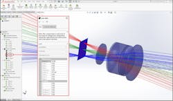
"At the end of the day, the design has to go back to the optical engineer to determine whether changes or updates are beneficial," says William Radigan, owner and principal engineer at Radigan Engineering (Albuquerque, NM). But optical engineers are sometimes skeptical about receiving a file from a mechanical engineer, based on past experiences in which systems failed because of something that wasn't caused by their lens design.
Giving mechanical engineers access to their designs requires trust. LensMechanix helps by opening communication with fully featured language during the back-and-forth iterations. Receiving a file in an OpticStudio format gives optical engineers more control over the design and ensures they have the latest file for validation. Mechanical engineers can catch and correct their own errors, avoiding repeated physical prototypes to identify problems. With less time spent iterating, optical engineers can spend more time designing new products.
Tackling other common challenges
Optimizing a design so that it achieves performance goals often means optimizing the whole design rather than specific elements. Although it is easy for an optical engineer to require very tight tolerances to ensure that the product comes as close to the design as possible, this overtightening can drive up the cost of production and pose significant problems in production. Optical engineers can include elemental and positional tolerancing data in their designs, and then make the information available to mechanical engineers in LensMechanix.
Many optical systems are made up of multiple configurations, such as zoom lenses and scanning systems. Multiconfiguration optimization is the process by which systems that have common elements are optimized as a group, as well as for each set of positions that are part of a configuration. For example, on a pair of binoculars, LensMechanix users can change the space between elements to adjust the focal length and thus the zoom and focus. That is, both the optical and mechanical design can be optimized to accommodate each configuration.
For designs that are exposed to different environments and temperatures, such as some telescopes and lasers, thermal expansion/contraction and pressure can change the structure's performance. For example, NASA's Hubble Space Telescope is exposed to extreme temperatures and solar radiation that can negatively impact sensitive components. Although mechanical engineers cannot perform full structural and thermal deformation analysis in LensMechanix, they can vary atmospheric conditions to evaluate impact on optical performance at critical temperatures and pressures.
Cort Stinnett is general manager of the New Ventures Division and Andy Ferris is product manager of LensMechanix, both at Zemax, Kirkland, WA; e-mail: [email protected]; www.zemax.com.