Modeling: Multiphysics software models multimaterial optical fibers fabricated via HPCVD
SUBHASIS CHAUDHURI and JOHN BADDING
Optical fibers have revolutionized communications technology, and in addition are being used in a variety of other areas such as the medical arena, sensing, cutting and drilling, defense applications, and light sources in the form of fiber lasers and amplifiers.1
The drawing technique conventionally used to manufacture optical fibers limits the materials that can be incorporated in them. Another approach, templated deposition inside hollow-core optical fibers using high-pressure chemical vapor deposition (HPCVD), has emerged as an important technique to incorporate different materials such as metals, semiconductors, and insulators in fibers, enabling the exploration of various properties of these materials.2
HPCVD to obtain step-index optical fibers
Using HPCVD, semiconductors such as silicon and germanium have been deposited inside hollow-core optical fibers to form step-index fibers that guide light by total internal reflection. Compared to silica glass, silicon and germanium have a much wider transparency window that extends well into the mid-infrared, high linear and nonlinear refractive indices, and a high damage threshold. These properties enable the use of these fibers for the delivery of high-power infrared (IR) light, nonlinear optical processes, and IR countermeasures.
The size of the core and the refractive indices of the core and cladding determine the number of optical modes that can propagate in these fibers. Multiphysics simulation software has been used to model various step-index fibers to understand the light-guiding properties of these fibers at various wavelengths and how it is affected by altering the core size.
HPCVD to obtain Bragg optical filters
Apart from total internal reflection, light can propagate in a fiber by several other mechanisms such as the formation of a photonic bandgap,3antiresonant reflection.4 Bragg fiber is a special type of fiber that guides light via the formation of a photonic bandgap. It consists of a hollow core bound by concentric alternating layers of high- and low-refractive-index materials, which gives rise to the photonic bandgap.5
Using a Bragg fiber, light can be guided in a hollow core. This has certain advantages over light guidance in a step-index fiber, such as reduced latency, low absorption loss, and negligible optical nonlinearities. Bragg fiber was conceptualized in 1978, but because of the structural complexity of drawing such fiber by traditional drawing techniques, very few Bragg fibers have been fabricated.6,7
It is even more difficult to incorporate robust refractory materials as layers for the Bragg fiber via the drawing technique. This limitation has been overcome by using the HPCVD technique to deposit materials inside a hollow silica capillary to fabricate a fiber, rather than drawing it. The light-guidance property of the fiber depends on a number of factors, predominantly the diameter of the hollow core, refractive indices of the layers, the thicknesses of the layers, and the number of layers. Multiphysics simulation has been used to model all these parameters to obtain a Bragg fiber design with high transmission.
Use of multiphysics simulation
COMSOL Multiphysics 5.1 was used for modeling the optical fibers. The governing equation is the Helmholtz equation:
Triangular meshing was used, keeping the maximum size of the mesh element at a quarter wavelength (λ/4). Perfectly matched layers with a cylindrical definition have been used to obtain the confinement loss of these fibers.
Modeling of step-index fibers
Silicon step-index fibers have been modeled to obtain the maximum core size at which the fiber has single-mode guidance. The number of modes propagating in a fiber is given by the V-number of the fiber:
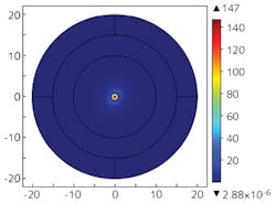
A V of <2.405 implies single-mode guidance for silicon fibers with core diameters below 360 nm at 1.55 μm wavelength, which has been corroborated by modeling. Figure 1 shows the light guidance in a multimodal 1.8-μm-diameter silicon fiber at a 1.55 μm wavelength.
Modeling of Bragg fibers
Different Bragg fiber designs have been modeled by varying all the parameters that affect the guidance properties, such as refractive indices of the layers, their thicknesses, and the number of layers. A wide range of material systems has been studied, including silicon (n = 3.4777 at 1.55 μm) and silica (n = 1.444 at 1.55 μm), silicon and germanium dioxide (n = 1.5871 at 1.55 μm), silicon and zinc selenide (n = 2.4556 at 1.55 μm), and silicon and silicon nitride (n = 2.4629 at 1.55 μm). The size of the fiber core in these models has been kept constant at 150 μm.
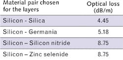
The best light guidance is provided by the layers that have the highest refractive-index contrast. To corroborate this statement, each of the different material systems was modeled with just one pair of quarter-wave-thick layers, keeping the wavelength constant at 1.55 μm. The lowest-order optical mode obtained corresponding to the lowest optical loss is the HE11 mode. The optical loss for each system is shown in the table.
It should be noted that these results include only confinement loss, which is the major source of loss in these fibers. Other types of losses, such as scattering loss, that may also affect the guiding property of these fibers have not been accounted for in these models.
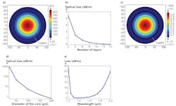
Figure 2a shows the associated mode for the silicon-silica system. Owing to its highest refractive index contrast, the silicon-silica system produces the lowest loss. Thus silicon and silica have been chosen as the layer materials for fabrication of the experimental Bragg fiber. It is known that increasing the number of layers decreases the confinement loss of the fiber - this has been verified by modeling fibers with different numbers of layers.Figure 2b shows the confinement loss as a function of the number of layers for a silicon-silica Bragg fiber. All the layers are a quarter-wave thick. As evident from the plot, the confinement loss decreases with the increase in the number of layers.
Figure 2c shows the mode for a Bragg fiber that has 14 layers. A similar effect is observed in fibers with layers of different materials, but the rate of decrease of confinement loss with the increase in the number of layers is much less. So for a fiber that has a higher index contrast between layers, lower loss can be achieved with fewer layers when compared to a fiber with low index contrast.
So far, the diameter of the core has been kept constant at 150 μm. The confinement loss of the fiber also increases with a decrease in the core size, which has been demonstrated through modeling four layered fibers of different sizes (see Fig. 2d). In this case, the thicknesses of the layers have been kept the same while the core size has been varied.
Spectral calculations have been done for the Bragg fiber to find its relatively low-loss region. Figure 2e shows that a four-layered fiber has a wide low-loss bandwidth of around 300-400 nm.
Experiment and results
The HPCVD technique has been used to fabricate step-index fibers and Bragg fibers. Silane (SiH4) gas, along with helium under a total pressure of 35 MPa, is introduced inside a hollow-core silica fiber while it is being heated externally. Under these circumstances, the silane decomposes and deposits along the inner walls of the fiber. This deposition continues until the core is completely filled with silicon to form a step-index fiber. Fibers with different core sizes can be created using this technique.
As found from numerical calculations and COMSOL modeling, when the silicon core size is below 360 nm in diameter, the fiber becomes single-mode at 1.55 μm. (It should be noted that if the core size is further decreased, at a certain point the core will no longer be able to support a confined mode and the light will leak into the cladding.) Germanium step-index fibers can be fabricated using the same technique by using germane (GeH4) as the precursor gas.8
To obtain a Bragg fiber, a 150-μm-core-diameter hollow fiber (see Fig. 3a) has been coated on its inner diameter with a thin film of silicon deposited by the HPCVD technique, rather than filling it up completely as in the fabrication of step-index fibers.9 Tuning the deposition conditions can precisely control the thickness of the silicon layer. This is followed by partial oxidation of the silicon layer under a temperature of 850ºC to form a pair of silicon-silica layers. This process is then repeated to increase the number of layers. The thickness of silicon deposited is adjusted, taking into account the increase in volume during oxidation. The thicknesses of the layers required for good transmission are based on the modeling result obtained from the COMSOL software. Figures 3b and 3c show scanning-electron-microscope (SEM) images of layers deposited using this technique.Multiphysics software provides powerful modeling functions that have been used to design step-index and Bragg fibers. Based on those designs, different fibers have been fabricated by using the HPCVD technique. Using modeling, different parameters can be tuned to obtain fiber designs that can have good transmission at various wavelengths. These fibers have potential use in high-power delivery of various wavelengths of light, ultrafast physics, sensing, medical applications, and other applications.
REFERENCES
1. W. A. Gambling, IEEE J. Sel. Top. Quantum Electron., 6, 6, 1084-1093 (2000).
2. P. J. A. Sazio et al., Science, 311, 5767, 1583-1586 (2006).
3. J. C. Knight et al., Science, 282, 5393, 1476-1478 (1998).
4. N. M. Litchinitser et al., Opt. Lett., 27, 18, 1592-1594 (2002).
5. P. Yeh et al., J. Opt. Soc. Am., 68, 9, 1196-1201 (1978).
6. Y. Fink et al., Science, 282, 5394, 1679-1682 (1998).
7. K. Kuriki et al., Opt. Express, 12, 8, 1510-1517 (2004).
8. J. R. Sparks et al., Annu. Rev. Mater. Res., 43, 527-557 (2013).
9. J. Chaudhuri et al., "Hollow core silicon-silica Bragg fiber," CLEO: OSA Technical Digest (Optical Society of America), STu1N.5 (2015).
Subhasis Chaudhuri is in the Department of Chemistry and John V. Badding is in the Department of Chemistry, Department of Physics, and Materials Research Institute, all at Pennsylvania State University, State College, PA; e-mail: [email protected]; http://chem.psu.edu.


