Optics/Fluorescence Imaging: Facilitating fluorescence with optical filtering
BRIAN MANNING, MICHAEL STANLEY, and JEFF CARMICHAEL
It is hard to overestimate the impact fluorescence imaging has had on life sciences. Fluorescence has advanced the field dramatically, and has become the basis for numerous bioimaging approaches and applications.
But achieving excellence with fluorescence techniques is not straightforward. Optical filtering provides a major source of enhancement for fluorescence techniques—enabling image contrast maximization, maintenance of image quality, and delivery of better outcomes. Let's look at a few examples.
Ratiometry
Ratiometric imaging involves the division of one image by another image, resulting in a measure of some biochemical parameter. As an example, by employing ratiometric imaging in living cells, changes in localized, unbound intracellular calcium concentrations may be tracked over time. This provides a record of physiologically relevant cellular processes—a sort of biochemical signature of a cellular event.
Ratiometric dyes are fluorochromes with dual-excitation and/or dual-emission characteristics that enable the measurement of these intracellular parameters. An example is fura-2, which is frequently used to measure changes in intracellular calcium concentrations ([Ca2+]i). When bound to Ca2+, fura exhibits an absorption peak at ~340 nm, whereas in a calcium-unbound form, it absorbs at a peak of ~380 nm.
Because switching between single-band filter sets is relatively slow and also entails a risk of shifting the sample and subsequent misalignment of images, accurate measurement of rapid changes in fluorescence requires the use of filter wheels. Typical fura experiments use such a wheel to alternate between 340 and 380 nm excitation filters. Fluorescence measurements are taken by using a 470–550 nm or similar bandpass emission filter mounted within the microscope. Post hoc image analysis is then used to compare 340/380 nm ratios (or calcium-bound vs. calcium-free levels of fura).
FRET
One specialized ratiometric application is Förster (or fluorescence) resonance energy transfer (FRET) microscopy. FRET is a phenomenon whereby an excited donor fluorophore molecule transfers energy in a nonradiative process to a suitable acceptor fluorophore molecule. This transfer of energy is termed "nonradiative" because it occurs without the emission of a photon from the donor fluorophore. Instead, it involves the direct transfer of energy of a donor molecule in the excited state when its fluorescence emission spectrum overlaps with the excitation spectrum of an acceptor fluorophore. The resulting FRET signal from the acceptor is often referred to as "sensitized emission."
FRET can benefit greatly by the appropriate choice of filters. In widefield imaging applications, donor excitation filters should be chosen to avoid direct excitation of the acceptor molecule as much as possible. While it's never possible to entirely avoid direct excitation of an acceptor fluorophore, carefully chosen exciters will best exploit the difference between the spectra of the donor and acceptor. For applications involving laser excitation, such as confocal and total internal reflection fluorescence imaging, the most appropriate laser wavelengths should be used with appropriate laser clean-up filters.
Likewise, emission filters should be chosen to best separate the donor/acceptor spectra. For example, in some cases it may be best to red-shift the acceptor bandpass to minimize the detection of donor fluorescence emission, while in other cases this will limit detection of the acceptor emission too much and will be counterproductive.
Far from being a simple technique, FRET is computation-intensive. Because it involves a great deal of image processing and correction, it is best performed using either systems with external filter wheels (affording independent control of excitation and emission wavelengths), or image-splitting systems (allowing simultaneous acquisition of donor and FRET signals during live-cell imaging). Temporal resolution may be critical in FRET, depending on the dynamics of the model system.
Multiphoton excitation (MPE) and fluorescence lifetime imaging microscopy (FLIM) are other laser techniques often used in FRET imaging, each with its own advantages and disadvantages. Both approaches benefit from the use of polychroic mirrors, which reflect multiple excitation bands and transmit multiple emission bands.
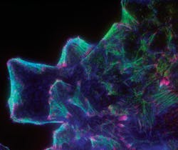
Controlling RWD for TIRF
Total internal reflection fluorescence (TIRF) microscopy was developed to restrict background fluorescence and increase signal-to-noise ratio (SNR). TIRF leverages light's ability to create an evanescent wave (or field) at a very limited range within the sample beyond an interface of two substrates differing in refractive index (see Fig. 1). In practice, this involves imaging a specimen that is in direct contact with a glass slide or tissue chamber. If the angle of the light is greater than the critical angle, the refractive index mismatch creates a field/wave with properties that are identical in frequency to the light. In other words, a fluorescent molecule that would normally absorb light at 488 nm can be excited by the electromagnetic field created by a 488 nm laser (or other monochromatic source) that is reflected off of the lower refractive-index material. Since the field will decay in intensity exponentially with distance, the resultant fluorescence signal will occur in less than 100 nm of the surface. This greatly reduces the z-axis signal, and correspondingly increases the sample's SNR.
Initial work in microscopy used prisms and beam-steering devices to bring light to the sample using an inverted design. Development of "through-the-lens" microscope systems (via high-numerical-aperture lenses) has made TIRF much more accessible, though this approach places an added burden on the filter/optics since the reflected beam is collected by the objective lens and follows the beam path backward. This means that the emission/blocking optics not only have to deal with huge amounts of excitation energy, but also that this light can be at high angles because of scatter and reflections. Whereas a typical laser emission filter must block excitation wavelengths to OD6, in TIRF, blocking must exceed OD8 in most applications.
In addition to the added blocking requirements, the dichroic mirrors in these applications must be incredibly stable in terms of reflected wavefront characteristics and surface flatness (see Fig. 2). A standard laser-scanning confocal requires a surface flatness of less than two waves per inch to control for reflected wavefront distortion (RWD) of the reflected laser. However, lasers used in TIRF applications require reflective surfaces with flatness values of less than a half-wave/inch to maintain a satisfactory RWD. The relevant surface flatness value is the one measured after coating, as the coating process exerts torque stresses on any substrate, including fused silica. Thus, producing dichroics to meet these flatness requirements is nearly impossible for some coating techniques and for some physical requirements of the substrates.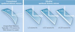
Chroma has developed the ability to control post-coating surface flatness to less than one half-wave/inch using a modified magnetron sputtering coater, coupled with proprietary methods for stress relief and starting with 2–3 mm-thick substrates at 1/10 wave flatness. However, we have also had to design and produce our own patented cubes/mounts/holders for performing TIRF in commercial microscopes, since standard microscope cubes will not hold these thicker substrates and cannot adjust the dichroic angles that make TIRF efficacious.
Blocking for Raman
Raman spectroscopy, used to study rotational, vibrational, and other low-frequency modes in a system, relies on the Raman scattering (inelastic) of monochromatic light, typically from a laser source. The light interacts with the specific bonds and electron clouds of a molecule to create a virtual energy state. The light's interactions with these phonons (molecular vibrations) in the sample shift the photon's energy up or down. These shifts in energy level (different rotational/vibrational states exhibited as either longer or shorter wavelength photons upon relaxation from the virtual energy state) reveal details of the phonon mode and, correspondingly, about the sample.
Raman scatter is so weak that the major challenge is to block both the intense laser light illuminating the sample and the Rayleigh scatter close to the laser in wavelength. Until recently, this could be accomplished only with holographic devices using multiple steps of dispersion, with the final signal going to a photomultiplier tube (PMT). With the development of more powerful and less expensive lasers and the achievements in interference filter designs and better CCD cameras, the newer Raman spectroscopy devices are both less expensive and easier to operate.
As filter manufacturers, our greatest challenge is trying to reduce/eliminate the excitation light (direct or scattered) from reaching the detector. This happens to be true of all fluorescence applications, but is even more important here because the primary job of the emission filter is not to transmit the emission, but rather to block the excitation load. It is also very important in this application, as in all involving lasers, that the laser source itself be clean by restricting the output since many lasers have emissions well outside their stated emission points. We therefore recommend a laser clean-up filter (10–20 nm at full-width half-maximum [FWHM]) coupled with an emission filter that blocks this band to over OD6. The dichroic mirrors in these applications must meet the requirements of the standard laser configurations listed elsewhere.
Confocal's unusual optics demands
Perhaps confocal microscopy's greatest advantage is its ability to optically section a specimen. Thanks to a unique arrangement of apertures, confocal microscopes produce images that are thin optical slices or sections of the specimen (see Fig. 3). A sample that might be several millimeters thick can be reduced to a focal field of less than 1 μm in the z-axis, for instance.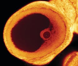
Confocal's field of illumination is restricted by an aperture called the pinhole. The field of view is also restricted by a pinhole, which is placed at the image plane conjugate to the illumination point and the first aperture. This confocal configuration results in less out-of-focus light reaching the detector, which increases the SNR by greatly reducing imaging volume.
Confocal systems place unusual requirements on the optical elements used for fluorescence imaging. Though it is commonly believed that a laser produces only one wavelength of light, in truth, most lasers produce harmonics and/or scatter of other wavelengths. While these secondary lines may be weak in intensity compared to the primary line, they can still reduce SNR—and if fluorescence emission happens to be in the same wavelength region as the harmonic (or other noise from the laser), the fluorescence signal may be completely masked.
The first element in the beam path is a laser clean-up filter, which is a modified excitation filter. Because of the collimated, coherent nature of laser light and the relatively small size of the beam, this optic should be ground and polished. The clean-up optic should also have very good transmission characteristics, including wavefront distortion of less than one wave per inch. The wedge (the deviation from perfect parallelism of the optic's outer surfaces) should be minimized to less than 1 arcmin, so that different clean-up filters can be used in the same system without need for realignment.
The clean-up filter, typically 10 nm FWHM, blocks extraneous light from the laser source (the maximum range would be from UV to 1200 nm) and is antireflective (AR)-coated for maximum transmission. With the new, more powerful lasers now available, AR coating may not be necessary for transmission efficiencies. However, these optics are made using interference layers with maximum reflection characteristics to avoid thermal damage—therefore, the AR coating will decrease surface reflections. To avoid reflecting back into the laser cavity, these optics are designed to be used at 3.5–5° angle of incidence (AOI). Diode lasers are known to shift slightly in emission wavelength as they warm up, so for these sources, we recommend a clean-up filter that is 20–25 nm wide.
The dichroic/dichromatic beamsplitter in a confocal system is selected for higher flatness specifications to improve wavefront distortion when compared to widefield epifluorescent illumination systems. As lasers have increased in power, concerns have grown about destruction of the primary mirror. But in well-designed dichroic optics, this is not a problem—at least up to 8-10 W with common beam sizes. Mirrors are AR-coated to minimize beam spot reflections and to maximize transmission. Polarization is another consideration with regard to mirrors. All optics at an angle to the beam path can act as polarizers, and most laser sources are themselves polarized.
As with all types of fluorescence imaging, the primary job of the emission filter is to block the excitation source. In confocal systems, this blocking does not typically involve as wide a region of the spectrum as epifluorescence. However, because of the power output of the laser lines, blocking may have to be specifically designed to be greater (perhaps >OD6) at the particular wavelength of laser emission.
Since the detector used for confocal imaging is typically a PMT, which forms an image one pixel at a time, emission filter optics may need not require grinding and polishing—but because resolution standards are increasing, these are not wasted efforts. Recent evidence suggests that an emission filter with a large wedge (beam deflection) may contribute to inaccuracies in morphometric measurements, which can be exacerbated by a long emission beam path.
While users should know that filter sets are built to address laser emission lines (instead of fluorochromes), fluorochrome manufacturers offer many choices that address the need to maximize absorption/excitation. In addition, a polychroic primary mirror can reflect multiple laser lines for convenience or speed.
Brian Manning is an application scientist, Michael Stanley is a senior application scientist, and Jeff Carmichael is technical and product marketing manager, all at Chroma Technology Corp., Bellows Falls, VT; e-mail: [email protected]; www.chroma.com.