Optical Manufacturing: Lightweight, bubble-free cast mirrors have no 'print-through'
The history of lightweight mirrors is based almost exclusively on designs using simple, repeating geometry with very few degrees of freedom. Conventional lightweight mirrors put far more complexity and engineering into the mirror mount than the geometry of the lightweight mirror itself. This is often driven by an inability and/or unwillingness to cast more intricate shapes and/or a belief that thickening the face is the best way to deal with "print-through" (mirror structural geometry appearing as associated errors in the wavefront).
In contrast, our approach involves designing and optimizing both the mirror and the mirror mount, often simultaneously. Engineering has shown that even after 13 years of design and engineering experience, an initial design can typically be improved by a factor of two. Although our experience and library of existing designs allows us to quickly create a new initial design and optimize it, the exact location and geometry of each rib is important and can only be done through real engineering.
Numerous traditional opticians believe that thin-faced and/or thin-featured lightweight glass mirrors cannot be processed with conventional equipment. The most common reason given is large-scale print-through, producing high mid-spatial-frequency (MSF) errors. Our engineering has never supported these claims, since polishing displacement is one of the cases we evaluate during the design phase.
In some cases, what is labeled print-through is simply annular ring zones caused by leaving a subdiameter tool in fixed locations for too long. This type of zone(s) is one of the most common artifacts of using subdiameter grinding and polishing tools. It occurs on all mirror types, not just lightweight mirrors.
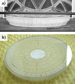
Bubble-free lightweight mirror
We recently finished a borosilicate bubble-free lightweight mirror with a 424 mm physical outside diameter (OD) and a clear aperture (CA) of 396 mm. The profile of the mirror is a mild double-conical with back flanges and has an edge height of 63.5 mm. Over the CA, the aspect ratio is 6.2:1, yet the mirror weighs only 4.32 kg. The mirror is rather steep at f/1.376 over the CA (see Fig. 1). The mirror has a 3-mm-thick face—40% thinner than previous mirrors we have produced in this size. It was finished with no detectable print-through and to a very smooth finish while using an over-arm machine. This thin-faced mirror was designed using our typical 0.25 psi of polishing pressure. For a 0.4 m mirror and full-diameter tool, that's a tool that weighs 22.7 kg, which is not a lightweight tool.
This is one of three different mirrors and dedicated carbon-fiber mirror mounts that Dream produced in-house for a client's adaptive optics (AO) project. Dream goes through an iterative process that uses finite-element analysis to show what the current lightweight mirror design will do, as well as the carbon-fiber mirror mount. The mirrors are analyzed for two distinct cases: polishing and gravity displacement. The former is an evaluation of how the mirror will perform during grinding and polishing. The latter is an evaluation of how the finished mirror will perform in final use, normally evaluated for a few different angles. Designs are modified and analyzed until design goals are met.
The weight, thermal time constant, and numerous gravitational penalties of a thick face and thick features, including everything downstream from the mirror itself, are substantial. These go mostly unnoticed because of the difficulties of getting a quality lightweight mirror and having it processed correctly, and because there are so few examples in circulation. The benefits are easy to see, even with simple means. Even when this mirror was 5°C different from ambient test temperatures, the mirror's boundary layer thermals would disappear in 20–30 s. Those engineers who understand the thermal issues within and around optics will recognize that this is a paradigm shift.
Test results show no print-through
Figure 2a shows a null image of the 396-mm-CA mirror with high MSF. Changes to the pitch-based polishing tool and a change to the eccentric drive of the over-arm machine were then made. Figure 2b shows the result of those changes—the changes made were fairly small and simple. All work was done with tool on top in our polishing room—68°F ±1°F year-round and humidity-controlled.
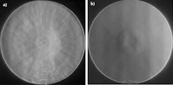
When compared to the null image in Fig. 2a, it appears the radial and annular ring ribs seen in Fig. 1b are printing through to the optical face. However, no settings were changed between the Fig. 2a optical surface and the Fig. 2b optical surface. Both used the same pitch, polishing pressure, stroke location, stroke length, stroke speed, spindle speed, polishing compound, room temperature, etc. We've seen a very similar pattern shown in Fig. 2a, but from a solid mirror. Although visually it looks like a good match to the ribs of this lightweight mirror, this work has shown that it does not mean the high MSF is coming exclusively from the lightweight mirror itself. If it were, then the surface in Fig. 2b would still show print-through since we did not change the polishing pressure.
The client's target radius for this mirror was 1089.9 mm, with a ±1 mm tolerance (±0.092%). During production, Dream used a carbon fiber radius rod that the company purpose-built and was quantified to 1089.9 mm, ±0.025 mm by an outside shop. Its CTE was ±0.2 ppm/°C. This provided a simple and quick means of initially working the surface to meet the radius requirement, then checking that radius during any optical testing iteration. The as-measured radius was 1089.69 ±0.050 mm, which is off by ~0.3 mm (-0.028%), but well within the client's ±1 mm tolerance for this mirror.
The simple changes made also gave us better control of the overall figure of the mirror because of the greater consistency in tool performance. Consistency is a must when working any optical surface because it offers the greatest level of control. Variables abound in optical finishing work. Dozens to hundreds of these types of variables are things seasoned opticians should have learned in their first few years of polishing on a daily basis. Yet the mysticism surrounding lightweight mirrors has persisted for nearly 100 years.
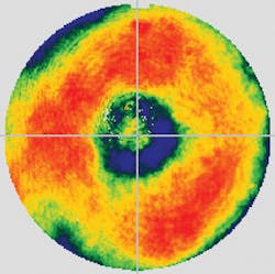
What we've seen is that the machine and the tool influence the smoothness, figure, control, and consistency of the optical surface far more than one might imagine. We've also seen that there are a huge number of variables, which can each influence the optical surface in a fairly large way. Our experience has shown that the same attention to detail that can make a solid mirror smooth, as well as provide better control over the process, can provide the same benefits for a lightweight mirror (see Fig. 3).
Opticians' claims that conventional machines cannot be used to finish lightweight mirrors and that all lightweight mirrors have print-through are obviously not true for everyone. These long-held beliefs are the largest reason lightweight mirrors are not used more often. The benefits of lightweight mirrors are enormous, but like anything that is not commonplace, very few truly understand the level and breadth of the benefits. Even after 13 years, we still feel that we are only scratching the surface of what can be done.
About the Author
Shane Santi
Founder and President, Dream Aerospace Systems
Shane Santi is founder and president of Dream Aerospace Systems (Nazareth, PA).