Modeling: Computer modeling boosts laser device development

Computer modeling can give valuable insight into the function of laser devices. It can even reveal internal details that could not be observed in experiments, and thus allows one to develop a comprehensive understanding from which laser development can enormously profit. For example, the performance potentials of certain technologies can be fully exploited and time-consuming and expensive iterations in the development process can be avoided. Some typical examples clarify the benefits of computer modeling for improved laser device development.
Example 1: Q-switched lasers
The basic dynamics of pulse generation in a Q-switched laser can be described with helpful formulas that reveal the influence of various laser parameters on certain performance parameters such as pulse energy and duration. However, it is often important to understand the impact of additional effects. For example, what effects will thermal lensing and gain guiding have on the performance of a Q-switched, single-transverse-mode laser?
Obviously, such questions cannot simply be addressed with experimental tests since these at most reveal what laser output is achieved in a few situations, but neglect the full impact of particular effects on the performance and do not allow a full system optimization.
A computer model that takes into account the transverse dimensions concerning beam profiles and excitation in the laser crystal can show in detail how the thermal lens with its aberrations affects the beam quality, for example, and to what extent the transverse dependence of the laser gain (gain guiding) influences the performance in high-gain situations. Note that the transverse gain profile changes substantially within the pulse duration because of saturation of the gain medium. Without such a model, it is close to impossible to properly quantify the importance of such effects.
The transverse beam profile in a typical actively Q-switched Nd:YAG laser varies with the number of resonator round trips (see Fig. 1). In addition to significant variations of beam size during the pulse, much stronger effects of that kind associated with a dramatic reduction in beam quality are observed if the path length in air is increased from 20 to only 25 mm, which would still be well within the stability range of that laser resonator.
This path length increase causes a frequency degeneration for higher-order modes—knowledge that could not be gained through experiments, but could be garnered through modeling exercises that quantify the sensitivity of the laser to gain-guiding effects, which depend strongly on the resonator design and not only on the magnitude of gain and the pump beam size. Such knowledge is essential for an efficient optimization process.
Example 2: Mode-locked lasers
Today, even fiber lasers can have impressive performance characteristics in the area of ultrashort pulse generation. This, however, requires operation in regimes where strong nonlinear and dispersive effects occur. Particularly in such cases, the relationships between device parameters and performance are often far from obvious.
Among other details, suitable parameters of saturable absorbers for passive mode locking—namely, the required modulation depth and the acceptable recovery time—need to be determined. Only a numerical model makes it practical to explore the limits of pulse stability and optimize performance. A "blind flight" trial-and-error approach in the lab can easily lead to time-consuming, costly, and frustrating iterations, making it nearly impossible to develop optimized designs.
Example 3: Ultrashort-pulse fiber amplifiers
High-energy optical pulses can be generated by amplifying low-energy seed pulses from a pulsed laser diode in a sequence of fiber amplifier stages. Between the amplifier stages, bandpass filters, Faraday isolators, and/or optical switches can suppress light resulting from amplified spontaneous emission (ASE). It is not obvious to which extent the mentioned methods are required.
Also, it is essential to know about other aspects such as occurring optical intensities, pulse distortions because of gain saturation, and possible nonlinear effects, amongst others. For many reasons, an uninformed trial-and-error approach is again inefficient.
Also, diagnosing problems in an experiment can be rather difficult because one cannot easily measure various essential quantities within the optical fibers or find out in the lab why such a system does not work well.
A comprehensive computer model of a multistage amplifier system can therefore be extremely helpful. It can be constructed in a much shorter time than an experimental prototype and at much lower cost. By revealing all relevant internal details, it allows one to refine the system design such that all known potential problems are safely avoided. The likelihood of unwelcome surprises in the subsequent laboratory experiments is then much reduced. One does not have to order expensive components without knowing whether they will work in practice.
Modeling can reveal how the pulse energies and forward ASE levels evolve in a four-stage amplifier system (see Fig. 2). The ASE is essentially removed by acousto-optic modulators after the first and second stages, and reduced with a bandpass filter after the third stage. The output is substantial in terms of average power, although the peak power of the amplified pulse is far higher. The same model also calculates the temporal shape of the resulting pulses (with strong distortions because of gain saturation) and many other quantities of interest.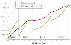
How to get started
Although laser development can greatly profit from computer modeling, many engineers and scientists hesitate before using this powerful method. But some tips and simple steps to follow based on practical experience can ease apprehensions about the method.
First, an important step is to identify the questions that should be answered by a model. For example, one may identify the need to understand the evolution of ASE powers along amplifier fibers, including their time dependencies.
Next, a suitable person should be found to actually develop the model-perhaps just one person within an R&D team or a research group. If there is no such person around (or no one has spare time), or if such needs do not arise often enough to justify the effort, an external consultant may be the right choice. Then, the consultant can evaluate the calculated results together with interpretations and recommendations and pass those to the team.
In many cases, an R&D team or research group will prefer to do the modeling work internally using some suitable software tools. In that way, the internal developers gain the most solid in-house expertise. They just need to select software tools that will serve multiple modeling needs in the future.
Different user interfaces
The easiest way to get started is by using software that consists of forms in which the developer enters various device and operation parameters like fiber length, input power levels, and wavelengths desired, and then obtains an output in text and graphical form that shows, for example, how optical power evolves within the device or how it changes with time (see Fig. 3).
Using these simple tools, models can be set up quickly and leverage a number of predefined diagrams that can make various adjustments through the available forms. For example, a developer could calculate the output power of an amplifier as a function of the pump power.
A common disadvantage of forms, however, is their lack of flexibility. The types of models and generated diagrams are more or less limited to those considered by the developer of the software. It may not be practical to put together multi-stage amplifier systems and to simulate complex operation cycles if the software developer did not offer these variants.
Much greater flexibility is obtained if modeling software also offers a script language that can be used to define the considered setup, to trigger calculations, and to generate the text or graphical outputs in any desired form. With a powerful script language, one can freely implement even the most sophisticated models and operation modes. For example, one could simulate multiple amplification and pumping cycles of an amplifier system as the output parameters stay constant, or automatically modify system parameters such that certain goals are met. However, potential users may have concerns that such a language would take too long to learn.
These two approaches—modeling software with forms or with a script language—are so fundamentally different that moving from forms to scripting may appear overwhelming. Fortunately, there are ways to conveniently combine the two approaches.
One possibility is that the software, when controlled with forms, can generate scripts based on the form inputs. The user can then go as far as possible using simple forms, but when the limits of that approach are met, the user can easily switch to script programming, starting with the automatically generated script rather than writing one from scratch. Also, forms may allow the user to inject small pieces of script code into the generated script, so that certain details (such as additional, special plots in a diagram) can be added without moving to script programming altogether.
Another possibility is that forms can be defined within scripts. This means that input and output fields, possibly including convenient graphical control elements such as selection boxes, can be defined in text form and associated with certain variables or functions rather than being hard-coded in the software. This allows the user to construct forms tailored to a certain modeling purpose, rather than being limited to those forms created by the software developer.
Advanced simulation and design software is an easy path to device modeling without being limited to basic tasks. The valuable time of laser engineers and scientists can be saved for more complex tasks rather than being used in overly time-consuming learning exercises.
Documentation and support
For any modeling task, documentation of methods and results is essential. The documentation must not only explain details of the user interface, but must inform the user what kind of physical model was used, what simplifying assumptions were made, and what limitations need to be considered. Unfortunately, software documentation is often neglected.
In case of doubt, competent technical support should be available—not only for helping with the handling of the software, but also offering detailed technical and scientific advice. For example, a beginner may find it difficult to decide which kind of model should be implemented for a certain purpose and which possibly disturbing effects need to be considered. Such support should come from a competent expert in the field rather than just a programmer.
About the Author
Dr. Rüdiger Paschotta
Founder and Managing Director, RP Photonics Consulting
Dr. Rüdiger Paschotta has done a Ph.D. and a habilitation in physics. He is author or coauthor of more than 100 articles in scientific journals, and of several books and book chapters. His best known publication is the online Encyclopedia of Laser Physics and Technology. He is also well known as a course instructor at conferences.
In 2004, he founded the company RP Photonics Consulting, offering technical consultancy, staff training courses, and simulation and design software for fiber optics, lasers, ultrashort pulse generation, and multilayer optics.