Glass/Ceramic Machining: Machining precision glass and ceramics: Choosing, specifying and avoiding pitfalls
MATTHEW WHITE
Traditionally, machined materials are metallic in nature: aluminum, stainless steel, steel, or Invar. But some precision engineering applications—like those with automation, extreme thermal environments, or precision optical surfaces—require high accelerations, stability, or response. Under such strains, some of those materials just can't quite meet the functional requirements. That's when engineers turn to glass, glass ceramics, and ceramics.
In the category of silicate glass, there is fused silica and ultra-low expansion fused silica as well as borosilicates. Glass ceramics—the second category—are annealed such that they start to ceramacize. Annealing results in a near-zero coefficient of thermal expansion (CTE). The ceramics category contains materials like silicon carbide, cordierite, and aluminum nitride. These materials have characteristic advantages and disadvantages as compared to traditional materials.
Breaking down the advantages
For applications needing dimensional stability, even a degree or two of thermal variation can be significant. A key advantage of glass and ceramic materials is that they have a lower CTE vs. metal—even Invar. Looking at the table, 316 stainless steel will expand the most, while glass ceramic expands the least. Variants can be as low as 0.007 parts per million per °C (ppm/°C). Overall, there is a huge thermal advantage in using glass and ceramic materials over traditional metals.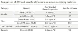
Silicon carbide's CTE is an order of magnitude better than stainless steel, but isn't as low as Invar, while silicon carbide's specific stiffness is much higher than Invar. Higher specific stiffness, calculated as Young's modulus over density, is another key advantage of these materials over metals. Specific stiffness is really a comparative value: the higher the number, the stiffer the material. The thermal expansion of ceramics isn't as good as that of glass ceramics, but for silicon carbide, one of the stiffer ceramics, its stiffness is a huge advantage.
For lapped and polished parts, glass or ceramics can be processed more easily than metals using optical fabrication techniques—thereby incorporating optical features, such as a mirror surface that could be used for positional feedback systems.
Glass, glass ceramic, or ceramic?
Having narrowed down material choice to nonmetallics because of their relative advantages, designers choose between glass, glass ceramic, or pure ceramic options. Generally speaking, it's a balance between cost and performance. Glass ceramics often have better thermal-expansion performance, so if that's the key performance requirement, then they might be the best choice, despite higher costs.
In an application where heat is generated within the system and where that heat must be transmitted out of the system, know that glass ceramics tend to be less thermally conductive. If the need is to conduct heat out of your system, ceramics have a much higher thermal conductivity than glass ceramics or glass.
If stiffness is what's important, because of high acceleration or dynamic loading, then the increased stiffness of ceramic materials is an advantage over glass. If cost is primary, then glass and glass ceramics processing tends to be a little bit more cost effective compared to ceramics, because of the nature of the material. Ceramics are tougher materials, and can be harder to process taking more time than glass and glass ceramics.
To reduce ceramic-processing costs, some rough shaping, called green machining, may be possible. Many ceramics, like silicon carbide, can be molded or formed into a rough shape prior to sintering. The sintering process is what ultimately gives them their ceramasized characteristics. Shrinkage occurs during sintering, and variations of 10% to 20% before and after sintering are common, lowering dimensional control. So, while parts with loosely toleranced features are suitable, tightly toleranced features on a component must be machined and polished post-sintering, though the hardness makes the process more time-consuming.
Designing for the materials
Compared to metal materials, there are some important differences to account for during the design phase to ensure manufacturability of nonmetallics. The most important point is to respect the brittle nature of the materials.
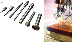
While metals are malleable, glass, glass ceramics, and ceramics are not, so their fabrication techniques are significantly different. Think about glass as a hardened steel-type material: once hardened, it can no longer be milled in the same way. Typically, these materials are processed with fixed-diamond grinding tooling (see Fig. 1). They are similar in function and appearance to milling tools, but the method by which they work is quite a bit different.
Glass and ceramics can be ground, similar to an inside-diameter/outside-diameter (ID/OD) grinding process, but can't be turned on a lathe with a pointed tool or a single-point tool like a metal. So, in designing, bear in mind that features often are going to be 3D machined or profiled, not turned.
Another difference to manage is that, while a metal component will first go into an elastic state causing it to deform or bend before its fails catastrophically, glass and ceramics are highly brittle, inelastic materials, failing catastrophically when the yield strength is exceeded. While a metal may dent from impact, these materials are instead susceptible to chipping and fracturing. Ordinarily, a failed component in these types of materials cannot be repaired.
Refrain from having corners and edges that are sharp. Sharp edges are prone to damage from minor impacts. Inside corners can lead to stress concentrations and be a seed location for a failure. Threading—possessing both inside corners and outside edges—isn't done in these materials, and certainly not threading under load. Glass or ceramic threads lack strength when it comes to holding force. Instead, a metal insert of some sort will usually be designed and bonded into the component.
Lightweighting limits
The technique of removing a portion of the material from a component while maintaining adequate structural strength and rigidity is called lightweighting. It is easy to lightweight components, and the technique has a long history. Fifty-percent lightweighting is commonplace. Lightweighting 80% or more is also achievable, but the designer should take care to design not only for function, but also for manufacturing. Any dynamic or static loads that the component is going to experience should be modeled, thus ensuring the strength is adequate.
Deep pockets, up to 75 mm deep, and 3 mm thin walls are common in glass or glass-ceramic materials. In specific cases, deeper and thinner is possible, and certainly so in ceramic materials. Every application is different and the range of implementation available is wide, but success comes down to doing adequate design up front while the component is being conceived.
Figure 2 shows an optical component that was lightweighted for an airborne application. All of the pockets show sharp inside corners. With no beveling, one would expect that if this part was FEA modeled with some type of dynamic or static loading, there would be stress concentrations between the pockets' floors and the walls. That would be an area of concern in manufacturing, and would be best addressed by adding radii to the bottom of the component's pockets to relieve that stress and create an appropriate safety factor. Keep those loads safely below the yield strength of the material.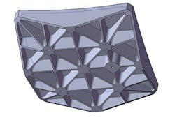
In designing a pocket or a feature, corner radii are important. Smaller radii result in less mass, but affect the size of the tools that have to be used. The process needed to create those smaller radii increases costs. A nice rule of thumb is that if radii are 9 mm or more in a lightweighting pocket, then fabrication is more straightforward. This rule works especially if you are talking about a deep pocket that is over 50 mm. When radii drop below 9 mm, it usually means additional processing is required. If deeper pockets or thinner walls are not necessary to meet the objectives, then save the expense. At a minimum, include fillet radii in the bottom of the pockets of at least 0.5 mm to minimize stress concentrations.
Cross-drilled holes-holes through walls-are common, but note when they are passing through features, or if the holes cross. The nature of the crossing can become challenging to fabricate. Have a conversation with the supplier to make sure you are designing geometry that's not going to cause unexpected difficulty. As an illustration of what's possible, Zygo can drill holes with a depth ratio of 100 times the diameter.
Machining with less stress on materials
With these brittle, hard materials, machining cycle times are longer, as with hardened metal machining. Even so, ultrasonic-assisted machining technology can reduce those times. In machine tools with ultrasonic capabilities, as the grinding tool rotates, it is also oscillating in the longitudinal axis of the tool, with amplitudes as high as 10 μm. The result is interruption of the contact between the tool and the part. The benefit is a reduction in the process forces on these brittle materials, keeping them below any yield strengths. This improves the life of the tool and the process reliability while making the process more efficient.
Unlike a cutting process, grinding is a fracturing process that results in some subsurface damage. Subsurface damage has to be post-treated in most cases. The less damage the better for the long-term viability of the component. Ultrasonic processing helps reduce subsurface damage.
More importantly, ultrasonics improve removal rates, reducing cycle times by half to as much as 90%. The interrupted contact improves lubrication, cooling the tool, and allows grinding particulates to be carried away, all of which contribute to greater speed.
Additional processing
In addition to computer numerical control (CNC) milling, these materials may be processed using optical production methods—loose abrasive lapping and polishing. With such processing, optical-precision metrology can be used to reach very high precision-tighter flatness, perpendicularity, parallelism, and true position.
Once lightweighted, a polished optic can present some print-through of underlying geometries, called quilting. If necessary for the application, subaperture polishing can remove this quilting. Good performance results in submicron to low-nanometer precision.
Polishing may be performed for a number of reasons, including cosmetic reasons or a shiny appearance. A polished surface is much easier to precision-clean than a surface that is ground. Of course, polishing may have an optical function. Coatings can make components optically reflective, electrically active, thermally reflective, or wavelength blocking, among other things. And different coatings can be combined in the same component.
Integration
Integrating the component into an application typically comes about as some sort of an assembly (see Fig. 3). For complex assemblies, multiple components of even dissimilar materials can be bonded together using epoxies or adhesives. Take into account stability and thermal and humidity changes. Consider the stress because of shrinkage of the bonding agent and the impact of that on the assembly over time.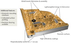
Another method, with higher environmental and time-based stability, is optical contacting, used mostly with similar materials. The cost of optical contacting assemblies is higher because the requirements on the bonding surfaces are tighter. Regardless of bonding type, it's common for tolerances below 5 μm to be achieved in relative position, perpendicularity, parallelism, and flatness.
The applications and the geometries of most glass and ceramic projects are unique, but development of glass and ceramic components begins by considering the available materials and their characteristics, then choosing according to best fit of weight, stiffness, and expansion. Pay attention to the design considerations, especially where they diverge from ordinary machining. With care and planning, the capabilities you can build into your component are extensive.
Matthew White is director of operations for the Zygo Extreme Precision Optics group (Richmond, CA); e-mail: [email protected]; www.zygo.com.