Microscopy and Raman Imaging: Open-system Raman microscopy
CYNTHIA HANSON and ELIZABETH VARGIS
Imagine accepting a new position to start up and manage a lab. Your modest budget for research equipment doesn't allow you to purchase what you really need, a Raman microscope—but you've inherited a fluorescence microscope from the previous scientist. What do you do?
Faced with this scenario at Utah State University, our solution was to transform the inverted epifluorescence microscope into a Raman system. The result not only saved money, but also allowed greater flexibility than a typical commercial Raman microscope would have. Before describing the setup, though, a brief exploration of Raman spectroscopy will help explain why certain instrumentation is needed.
Raman basics and equipment needs
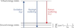
Raman spectroscopy relies on detecting light scattering events. Elastic (Rayleigh) scattering occurs when light interacts with matter and there is no change in the wavelength of the scattered light. By contrast, Raman scattering happens when the wavelength of light changes as it interacts with a molecule (see Fig. 1). The different wavelengths seen in Raman scattering are used to identify and study vibrational, rotational, and bending forces within chemical bonds of a molecule. Because Raman scattering occurs only about once in every million scattering events, it is an inherently weak signal amid a very strong Rayleigh signal-so equipment must be tailored to detect Raman scattering.
Primary components of a Raman system include a single-frequency laser, spectrometer, charge-coupled device (CCD), and appropriate software to analyze the data. It is important to use a single-frequency, wavelength-stabilized laser for Raman spectroscopy because the technique is based on the difference between excitation and emission wavelengths. Diode lasers are not considered suitable since some have a broad spontaneous emission background-and although this background is several orders of magnitude weaker than the laser light, it is considerably stronger than the Raman scattering signal. Diode lasers can also mode hop, or change their primary frequency, due to temperature fluctuations-an effect that is problematic because Raman signals are based on relative wavenumber measurements.
Typical Raman experiments use a continuous-wave laser; that is, a source that produces a constant beam of light during operation. In terms of an image detector, a good match for this is a CCD—a type of camera used to record the intensity of different wavelengths of light. There are many kinds of CCDs, and choosing the right one will depend on the application. For Raman spectroscopy, acquisition times on the order of seconds are appropriate.
To distinguish among different wavelengths, a spectrometer is used to spatially separate light according to wavelength. This spatial separation occurs as light hits a grating (see Fig. 2). Gratings are specified by the number of grooves per millimeter (g/mm) or lines per millimeter (l/mm). The more grooves or lines per millimeter, the better the spectral resolution. However, this comes at a tradeoff with the range of wavelengths that can be detected per acquisition. The blaze angle also plays a role, as it determines the efficiency specific wavelengths. When purchasing a spectrometer, the desired resolution, wavelength range, and associated efficiency need to be considered.![FIGURE 2. Illustration of how a grating separates light according to wavelength and a typical structure for the surface of a grating [1].](https://img.laserfocusworld.com/files/base/ebm/lfw/image/2015/12/content_dam_lfw_print_articles_2015_05_1505lfw_han_f2.png?auto=format,compress&fit=max&q=45?w=250&width=250)
There are aspects of spectral software to keep in mind such as compatibility with the camera. Often, spectral software is included with the camera. But in any case, certain capabilities are useful. For example, because Raman signals are often overshadowed by fluorescence, especially when using excitation wavelengths in the visible range, background correction or subtraction features can be helpful.
System operation
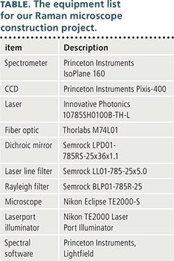
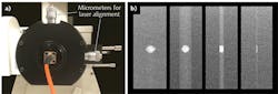
A list of all the equipment we used to transform our fluorescence microscope into a Raman instrument is provided in the Table. In our setup, an open-beam laser with an excitation wavelength of 785 nm is focused onto a fiber-optic cable. The fiber optic is then attached to the back of the microscope using a laser port illuminator. As the beam makes its way to the filter cube, it first passes a laser line filter to remove Raman scattering from the optical fiber. Next, the beam is reflected upwards by a 785 nm long-pass dichroic mirror. At that point, the laser beam enters the objective lens and is focused on the sample. The scattered light from the sample is collected by the objective and directed to the dichroic mirror. The Raman scattered light is transmitted through the dichroic mirror while Rayleigh scattered light is reflected. Finally, the Raman scattered light is filtered using another long-pass filter to remove any of the remaining Rayleigh scattered light (see Fig. 3). The light then hits a mirror to exit the microscope and enter the spectrometer. After the light is separated according to wavelength, it reaches the CCD where it is measured.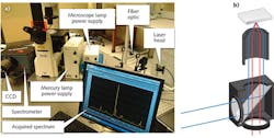
Build-or-buy tradeoffs
Why would you go through the trouble of building a Raman microscope system when you can easily purchase a system? Cost and flexibility.
For starters, commercially available epifluorescence microscopes typically range from $10,000–30,000, while a basic Raman microscope system starts at $80,000–100,000. Our in-lab built system was less than $65,000 for both applications.
But flexibility may be an even greater selling point. Typical Raman microscopes are designed as closed systems, where the sample sits in an isolated chamber during analysis. When building your own system, you can design it as an open system, allowing greater flexibility design and future applications. For example, if your sample needs to flow through a microfluidic device during analysis, an open system would be more advantageous. It also allows flexibility for future modifications such as the use of different laser wavelengths or pulsed lasers. This task would include switching fiber optic cables to a new laser and installing a new filter cube block. By contrast, upgrading a commercial system would be quite expensive.
Although purchasing a commercially built Raman microscope system provides easier setup and lets you take advantage of technical support, there are situations where building your own is more appropriate—or may be the only option available.
REFERENCE
1. Q. Liu, J. Wu, and M. Chen, Opt. Eng., 52, 9, 091706–091706 (2013).
Cynthia Hanson is a graduate research assistant and Elizabeth Vargis, Ph.D., is assistant professor of biological engineering, both at Utah State University, Logan, UT; e-mail: [email protected]; www.vargislab.com.